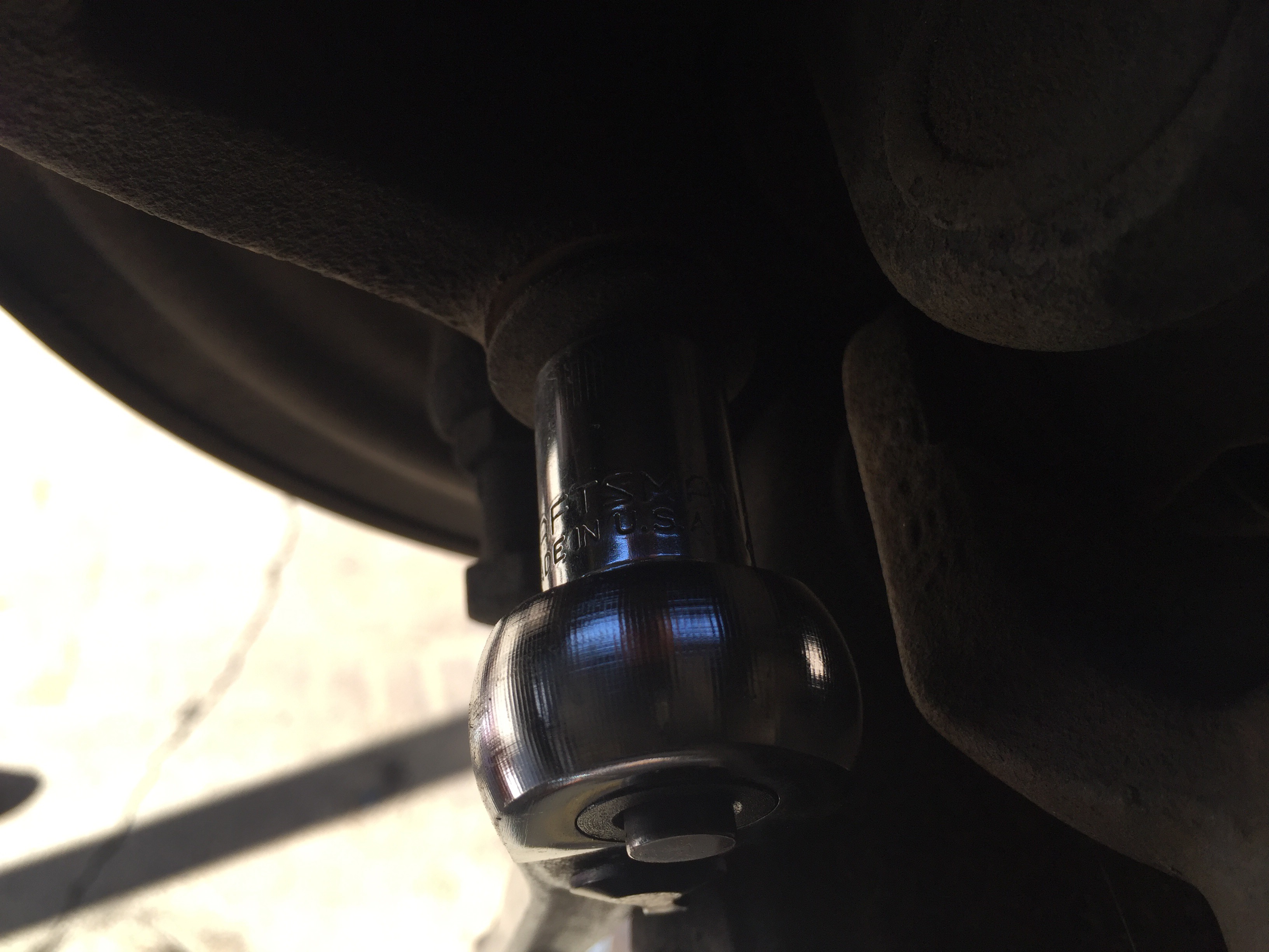
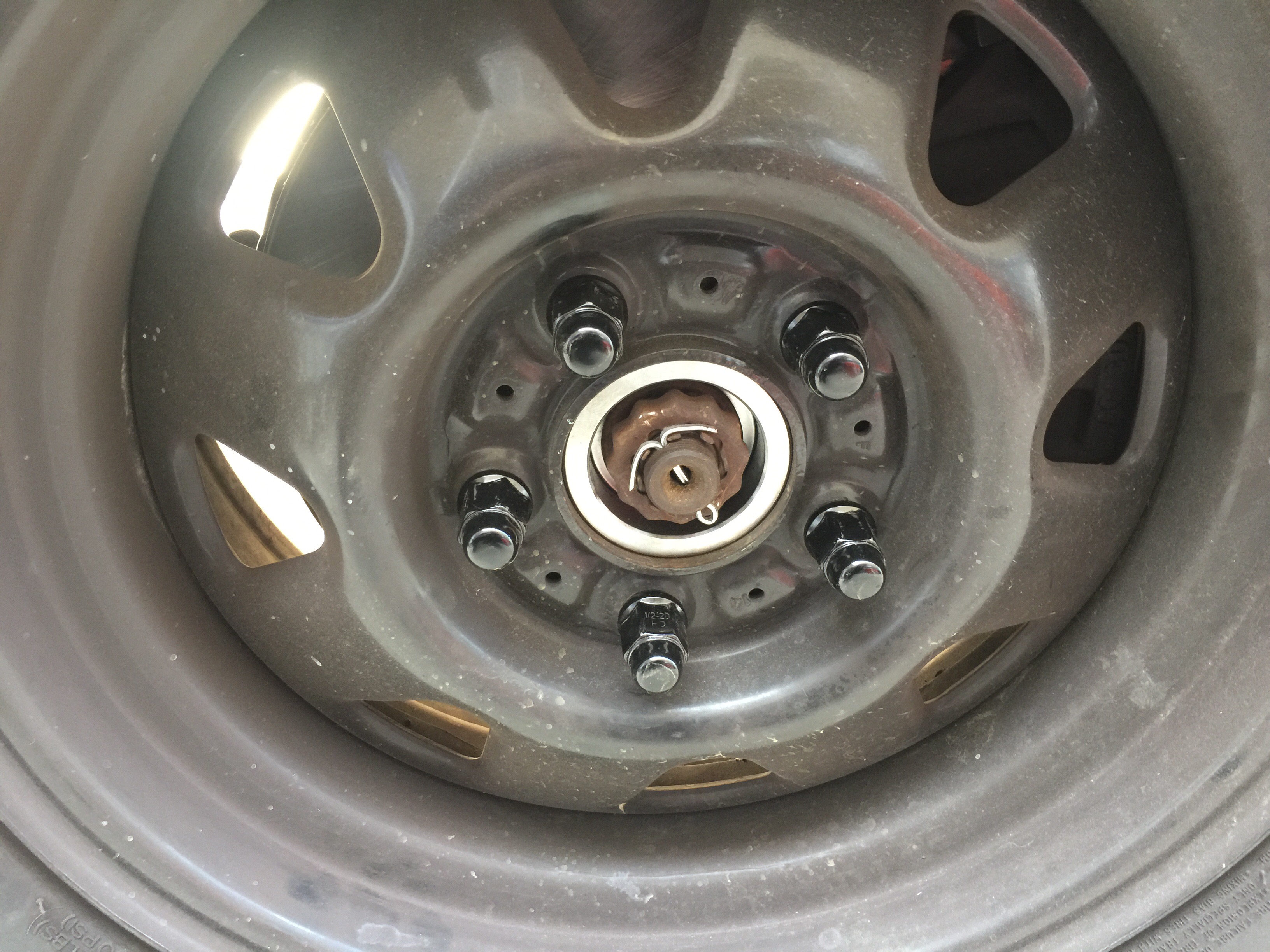
Now that I had some good, used Axle Shafts with new U-Joints ready to go, it was time to remove all the Central Axle Disconnect (CAD), original equipment. First, I pulled the cotter pin and lock ring from the axle nut. Next, I took a 36mm socket and a HUGE breaker bar, and broke the axle nut loose on both sides.

Once the axle nuts were removed, I broke all the lug nuts loose and jacked the Jeep off the ground. I placed my jack stands under the axle and removed the wheels.

Once the Jeep was up, it’s was time to pull the old shafts out. To gain access to the old axle shafts, the calipers, brakes, rotors, and wheel hubs had to come off.
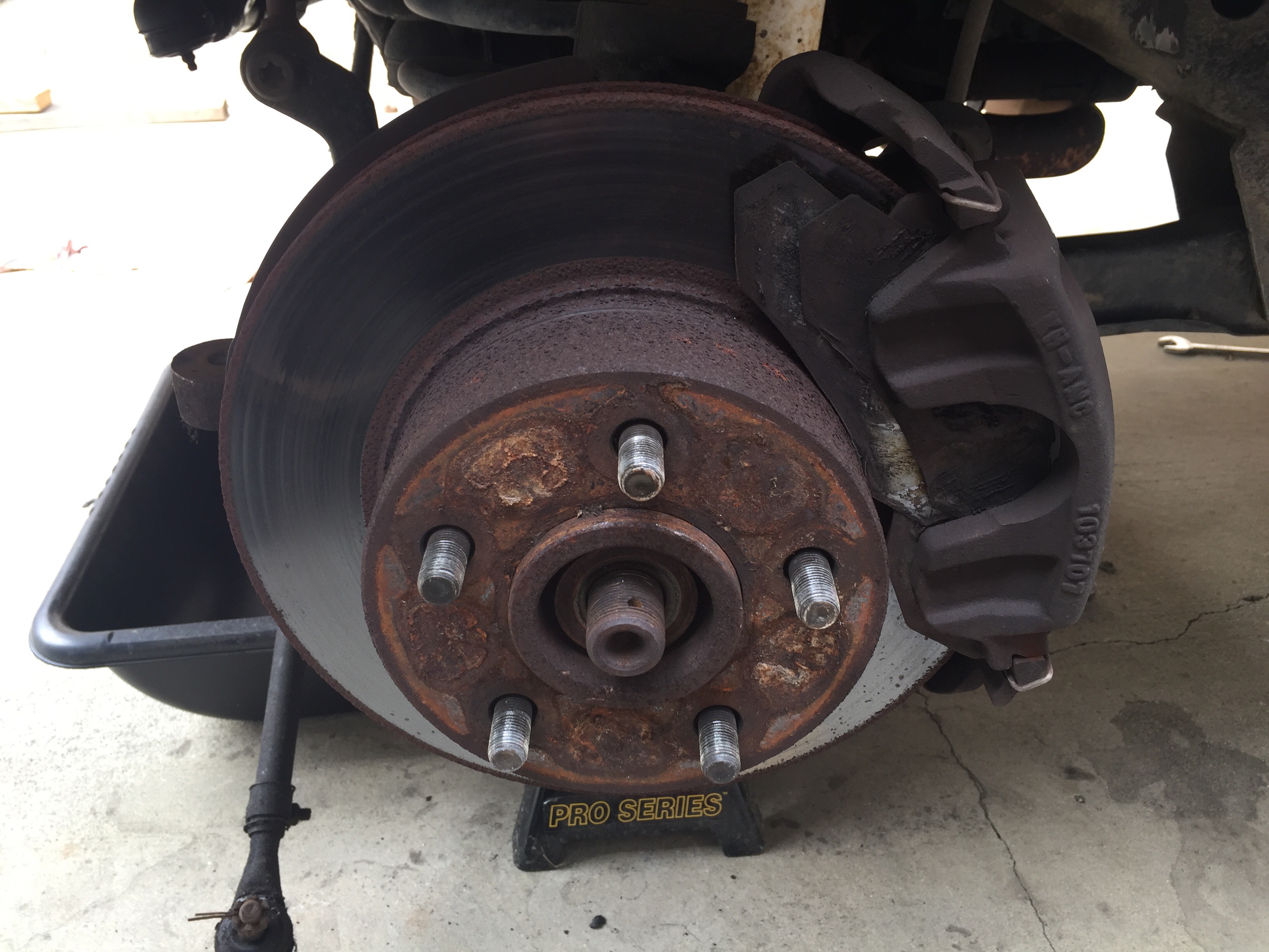
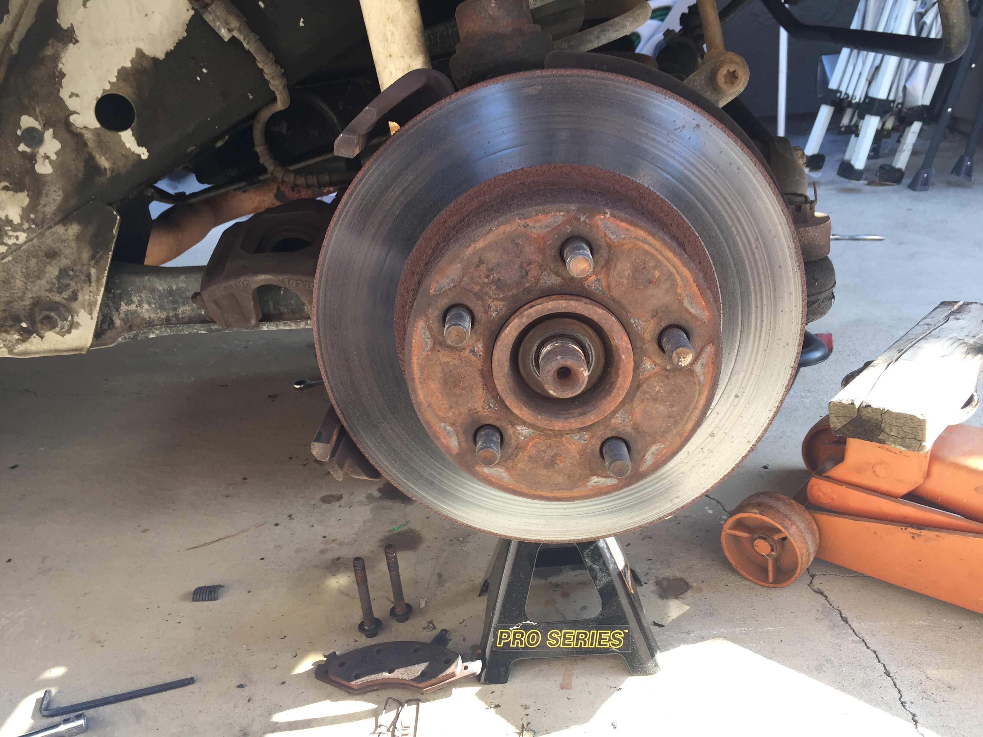
The wheel hub is held on by 3 bolts that require a 12 point, 13mm socket to remove them.
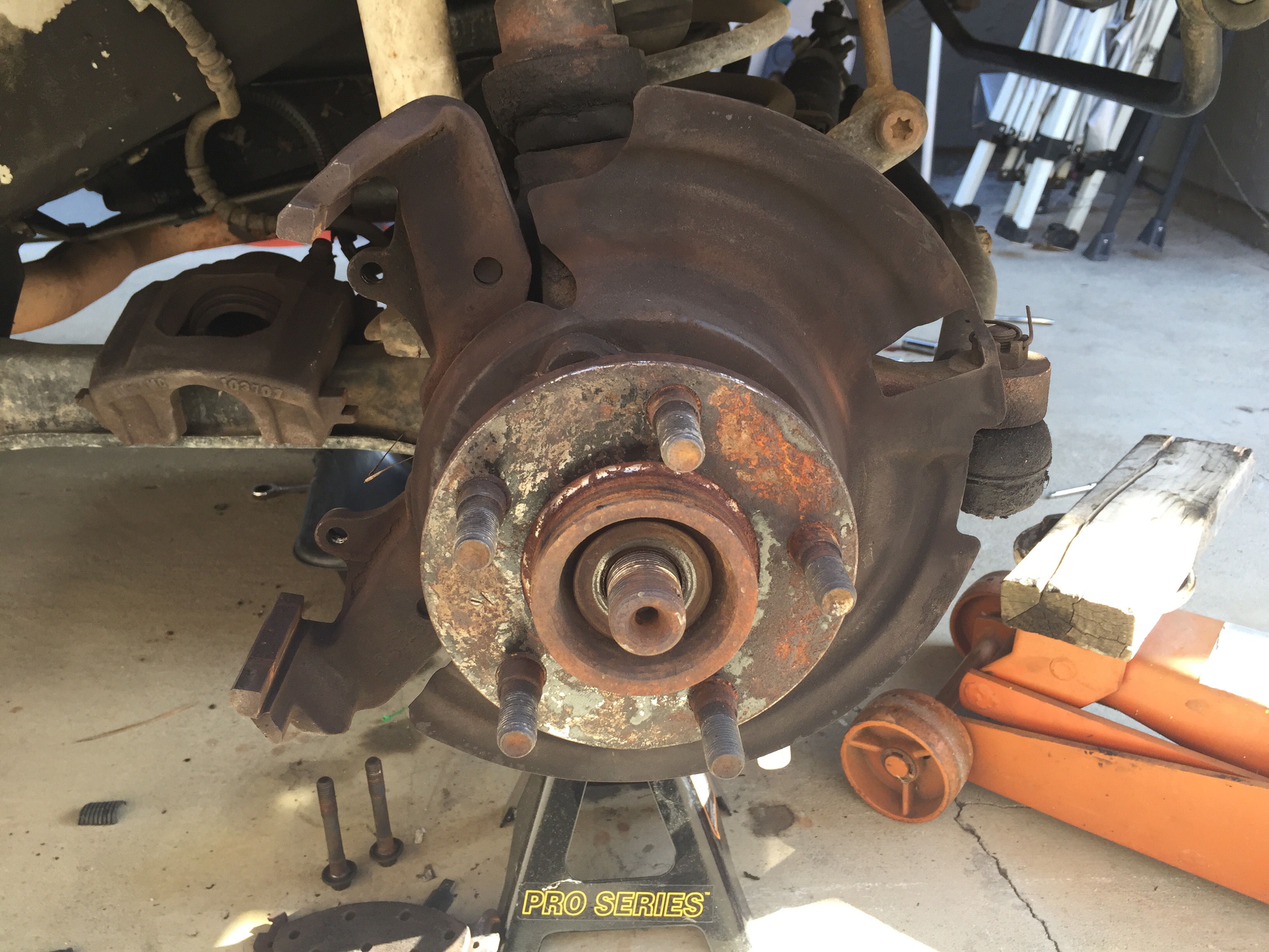
Once the three bolts are removed, tapping the hub with a dead blow until its loose will allow you to pull it off. After taking the hubs off on both side, you can now pull the short shaft out of the driver side and the outer shaft from the CAD housing, on the passenger side.


Now there are a few ways to get the intermediate shaft out of the axle but the way I did it was to pull off the CAD Vacuum motor and removed the collar and tried to pull the shaft out but ran into a problem.
The problem I had, only occurs on older model Dana 30’s with CAD, that have never had the shafts removed since they were installed (according to what I’ve read). My problem was that there was a C-Clip on the inner shaft where it goes into the carrier that wouldn’t allow me to remove inner shaft. From what I read, this C-Clip was installed at the factory to hold the shaft in while the axle was being assembled. You do not have to reinstall this C-Clip with the new axle shaft.

I just took a screwdriver and pried it off. It will come out easily. With the C-Clip removed, I fed the intermediate shaft out of the passenger side. Here is what the whole CAD axle system looks like out of the axle.


Here is a diagram of how the whole vacuum system works.

The red hose comes off the vacuum reservoir and has a constant vacuum on it. The red line travels to the vacuum switch on the transfer case and supplies vacuum to the whole system. With the transfer case in 2wd the switch provides a vacuum to the green port of the CAD vacuum motor which keep the CAD in the unlocked position. Once you shift the transfer case into 4wd HI or 4wd LO, a shaft in the transfer case activates the vacuum switch on the back of the transfer case and provides a vacuum to the Yellow line. The yellow line travels to the CAD vacuum motor and slides the axle lock collar onto the inner shaft to lock them together. The yellow line also “T’s” off to a white vacuum line. The white vacuum line activates the vacuum switch for the 4wd light on the dash. All of these vacuum lines will be removed once I remove the vacuum switch in the transfer case and replace it with an electric switch for the 4wd light on the dash. The vacuum switch is circled in green.

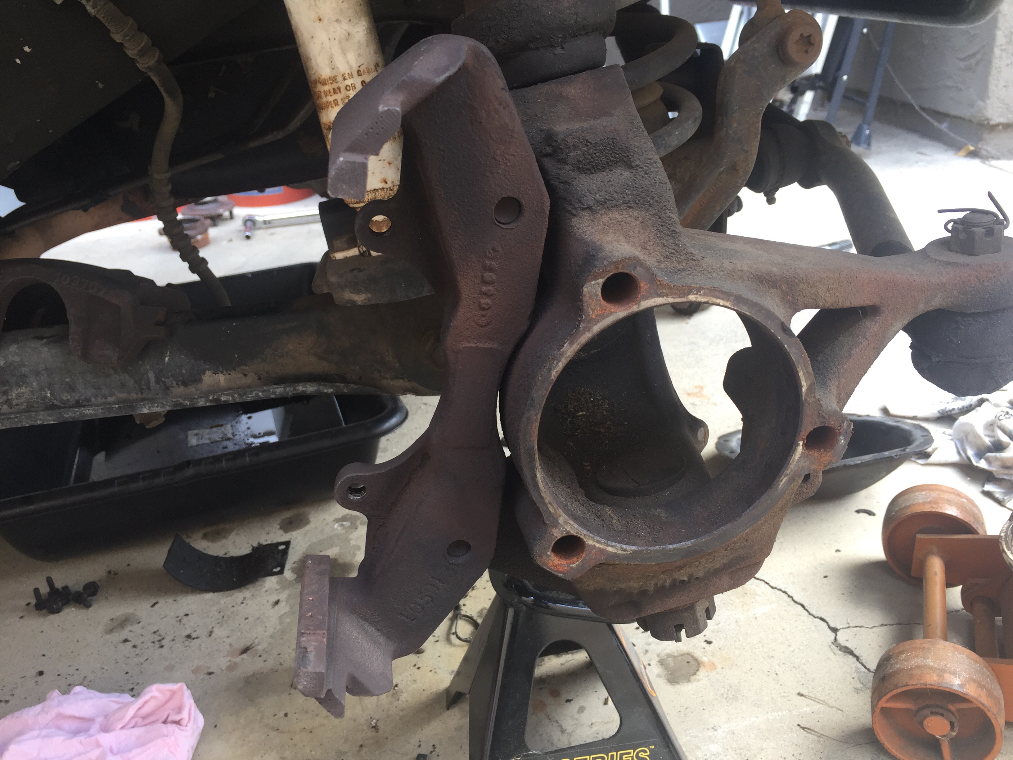
Before getting to that, there was more to be done with the axle. The next thing that needed to be done before install the new solid shafts was to install a new inner axle seal in the housing. The Rusty’s CAD Delete Kit, comes with a new seal.
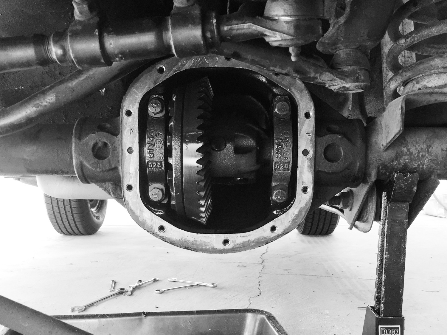
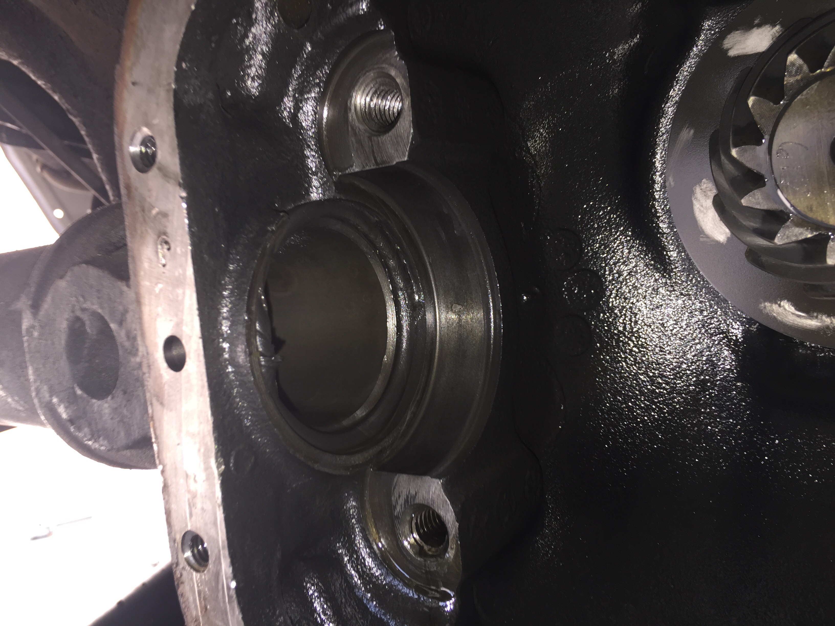
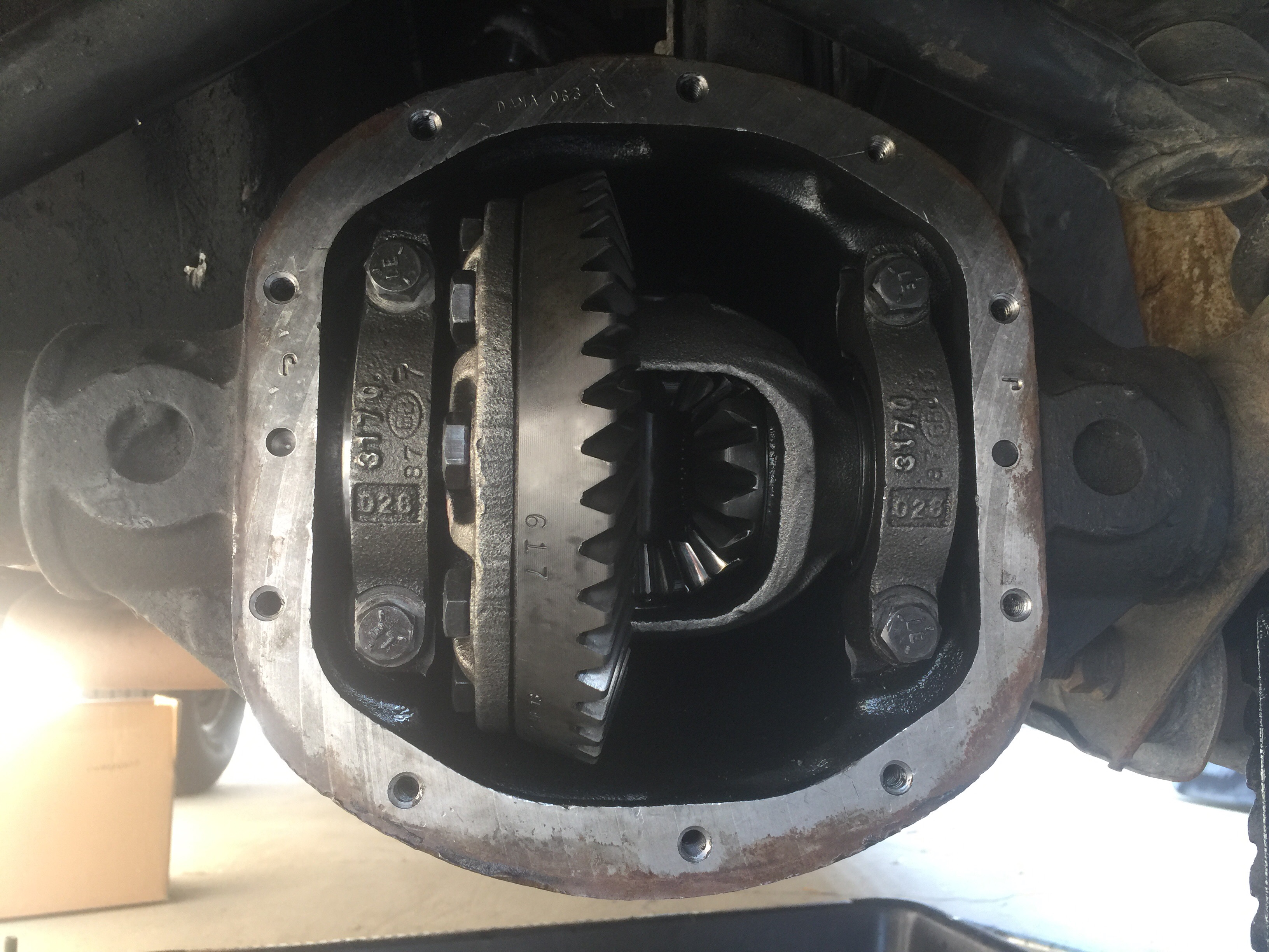
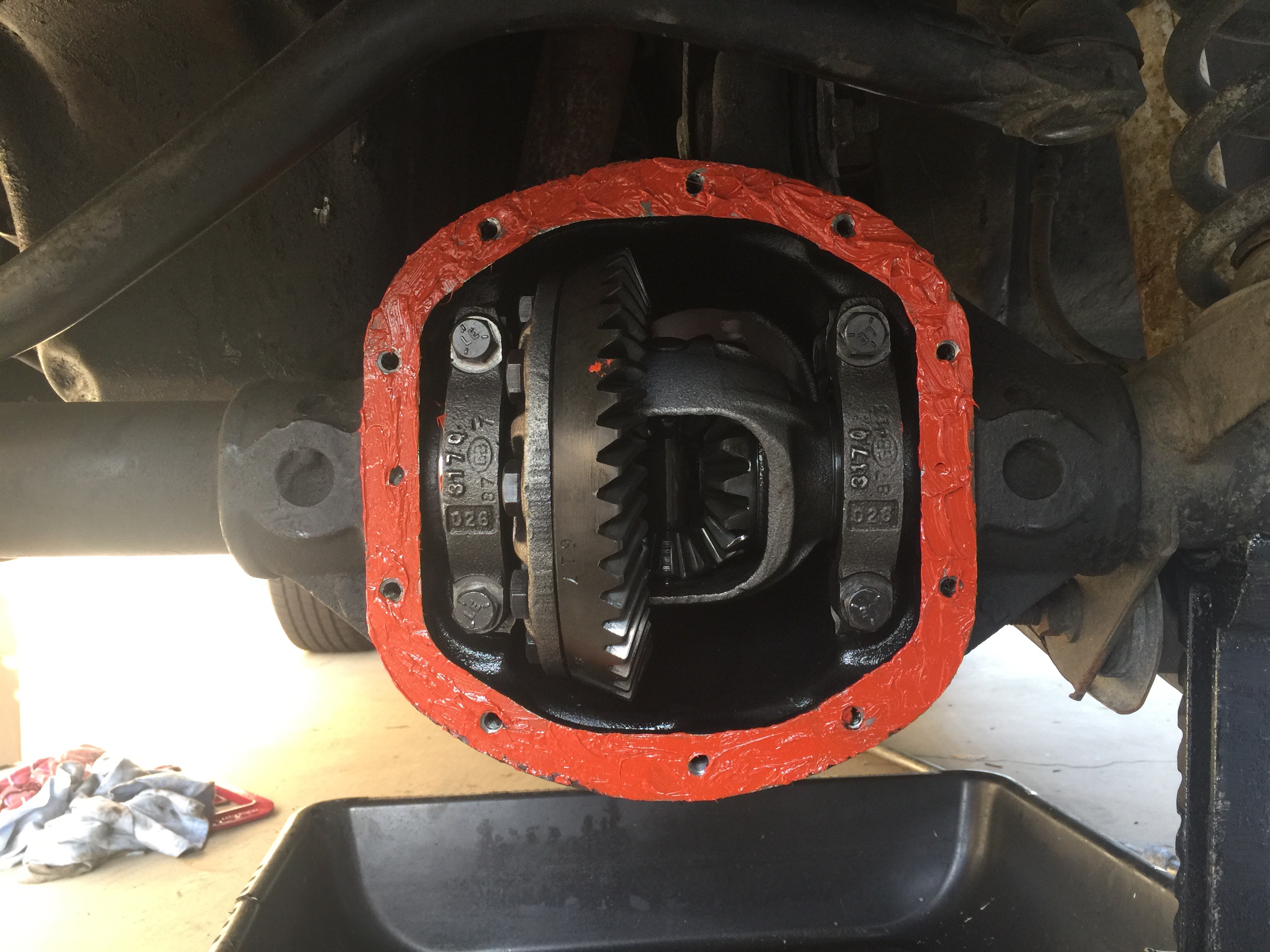
To install the seal requires the carrier to be removed from the axle. Before I removed the carrier bearing caps, I verified the factory put makings on the caps. Passenger side had a vertical “J” on housing and cap and the drivers side had a horizontal “J” on the housing and cap. Both “J”s were on the top of each cap for proper orientation. I used a 5/8” socket and ratchet to remove the the bolts from the caps and set them aside. I used a pry bar to remove the carrier. I pried between the ring gear bolts and the housing until the carrier started to come loose. PRO TIP: While prying the carrier out, hold the carrier with the other hand to ensure the carrier doesn’t fall on to the ground and crack a tooth on the ring gear. I made sure not to drop or swap the carrier bearing races. The side they were on when they came out is the same side they have to be on when the carrier goes back in. I set the carrier aside and was left with an open housing.
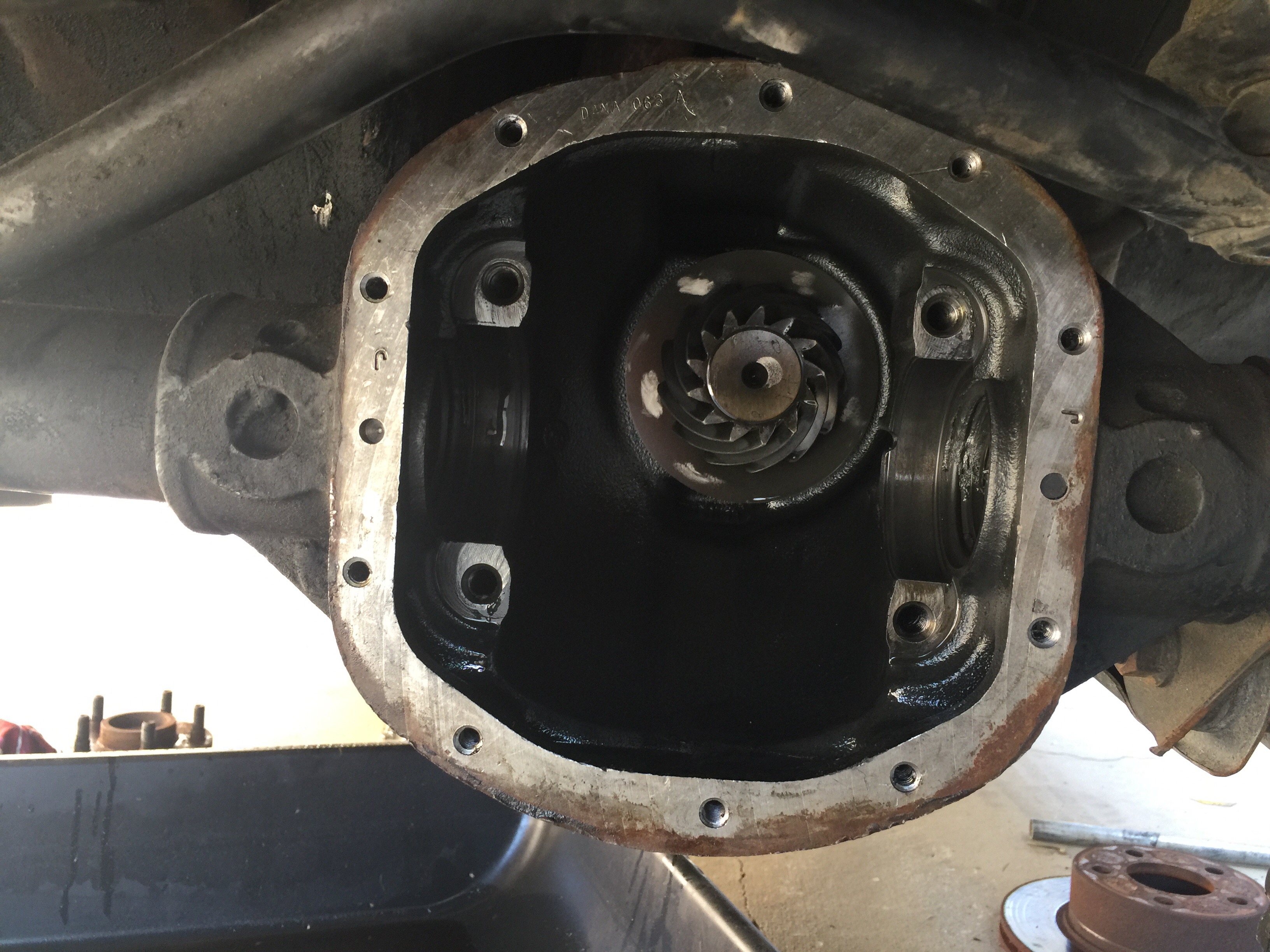
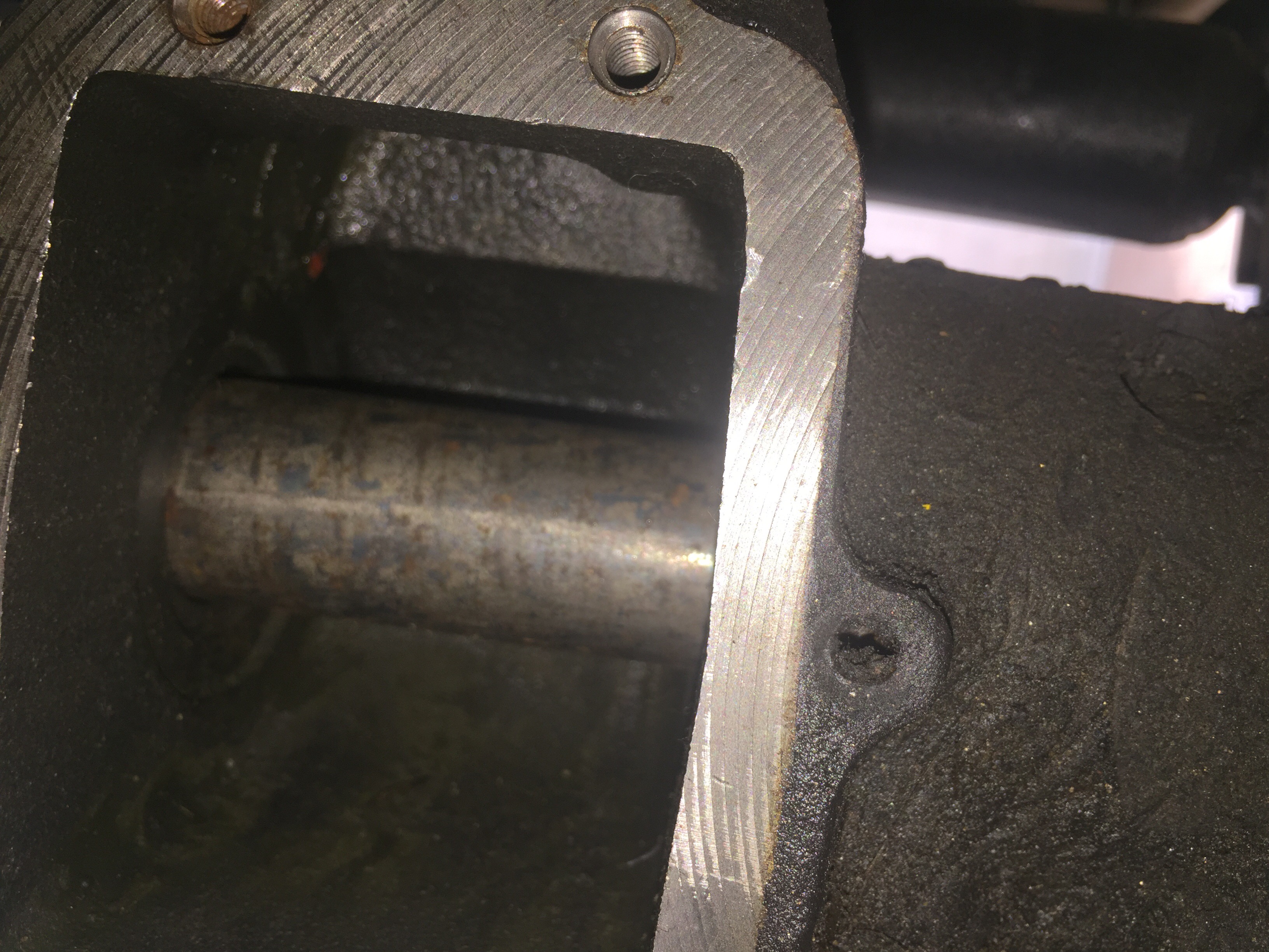
I cleaned the grease and gunk out of the passenger side axle tube to ensure a proper seal.
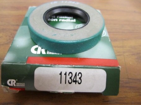
I used a 34mm socket with extensions to install the new seal but ran into a problem. The CR11343 seal was too big for the axle tube and ended up getting deformed once I got it in. Even making sure I put it in square didn’t make a difference. I took some inside dimensions of the axle tube and I came out to 1.972″ I.D. And the axle shaft measured out to 1.18″ where the shaft seals when its in the axle. The seal I ended up using what a National Seal #: 223050. This is a transmission seal for a 2003 Subaru WRX. The dimensions are 1.978″ I.D. and a shaft seal of 1.181″. The pictures shows the CR11343 seal from Rusty’s Off-Road on the left and the National Seal, part #: 223050, seal on the right.

You can see the seal on the left is slightly deformed. I put some RTV on the new seal for better sealing, then pressed the seal in with a 34mm socket and extensions. It was tight but much easier to install then the CR11343 seal.

I added some RTV to the outside edge of the new seal and axle tube since the factory sealant fell off while removing the old seal. I finished it off with a little grease on the shaft seal for smooth sliding of the axle shaft when I install it. I popped out the old driver side seal and installed a new one just because I already had the axle apart.

I used a Dana 30 Inner Axle Seal installation tool from Torque King 4×4 that a friend had when he replaced his axle seals, to install the driver side seal. It went in extremely easy with that tool.

I could only use it for the driver side seal because the passenger side seal tool was for replacing the passenger tube seal near the CAD not the inner seal from the kit. I let the RTV cure for 24 hours before reinstalling the carrier. I installed the carrier and put the caps on the proper sides and orientation.
I torqued the bolts for the carrier down to 60ft. Pounds. Before installing the shafts it was time to tackle the vacuum lines and clear some space in the engine bay. The red vacuum line is the only one to be concerned with. On mine, there is a black, rubber vacuum line coming from the vacuum reservoir that goes the the intake manifold near the back. Before it gets to the back of the intake, it “T”s off to the Red vacuum line in the CAD vacuum harness. I remove the red line and capped it with a 1/4” vacuum plug. After that is done, the vacuum harness is ready to pull out.

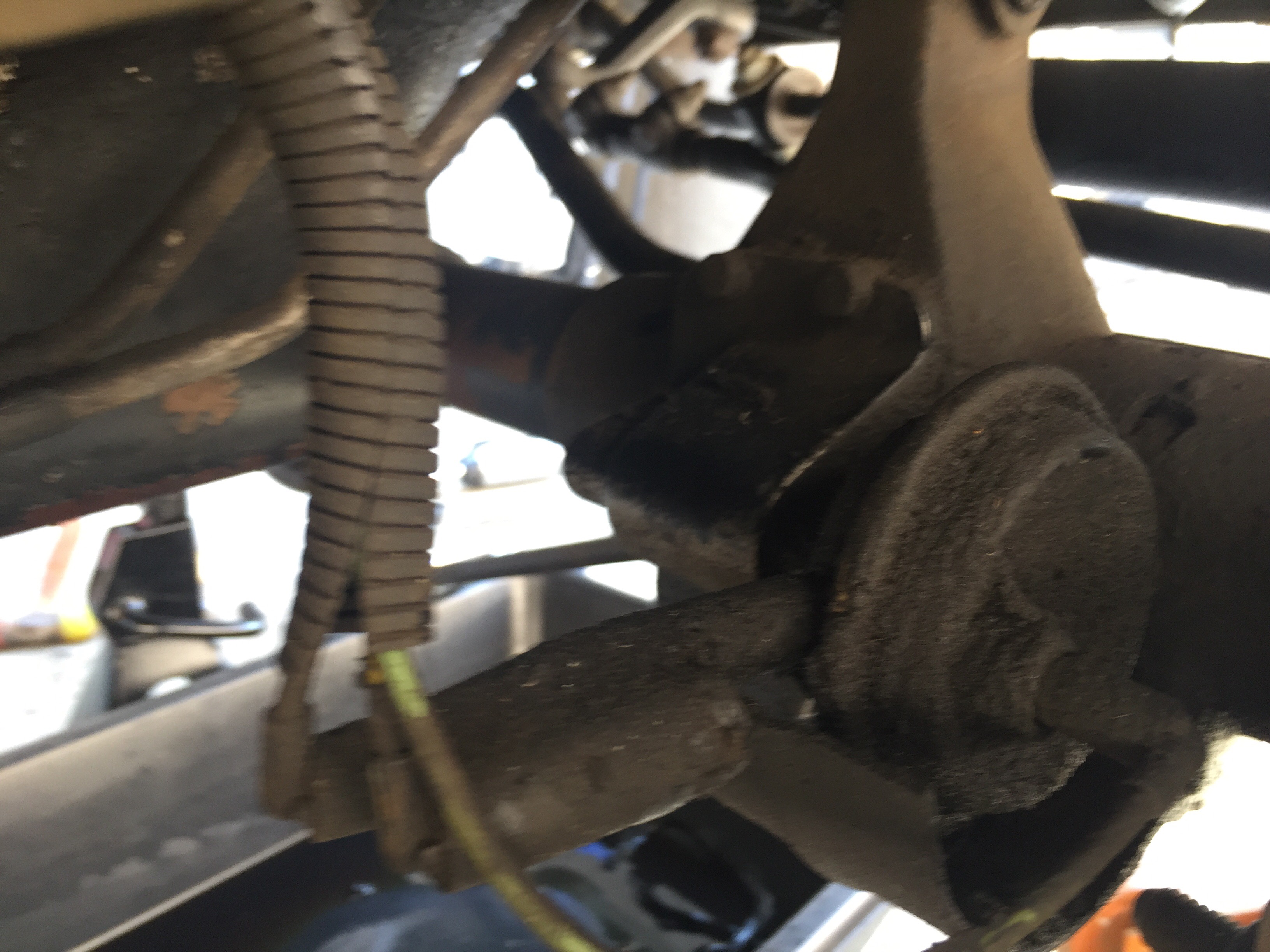
I disconnected the lines going from the CAD motor to the solid lines and set them aside first. I then removed the three lines in the engine bay from the hard lines and set them aside. Here is a picture of how the hard vacuum lines are mounted on the passenger side unibody rail.

I pried the hard lines from their clips and set them aside. Once those are out, I took my 10mm ratchet and removed the vacuum 4×4 light switch from the passenger side fender near the blower motor.

I disconnected the wires going to the light switch and set them aside for later. I pulled the lines going from the transfer case in to the engine bay and was done removing all the CAD vacuum lines. Here is a photo of the CAD system put together outside of the Jeep.
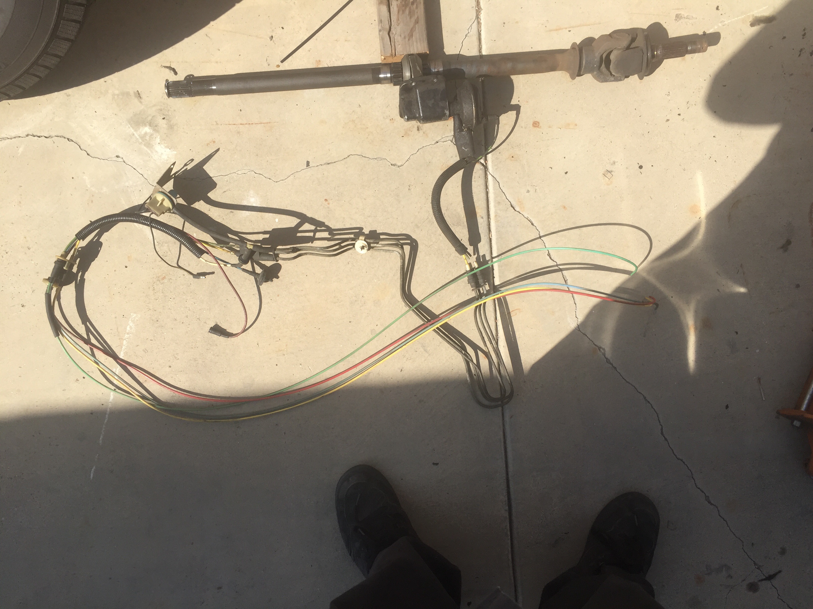
If you look closely, you can see a number of vacuum lines are broken on my harness which was the reason my jeep didn’t go into 4wd. Now, I won’t have that issue anymore. After pulling all the vacuum crap out, it was time to install the replacement shafts. First, I cleaned all the mating surfaces with Brakleen and a Scotch Bright pad.
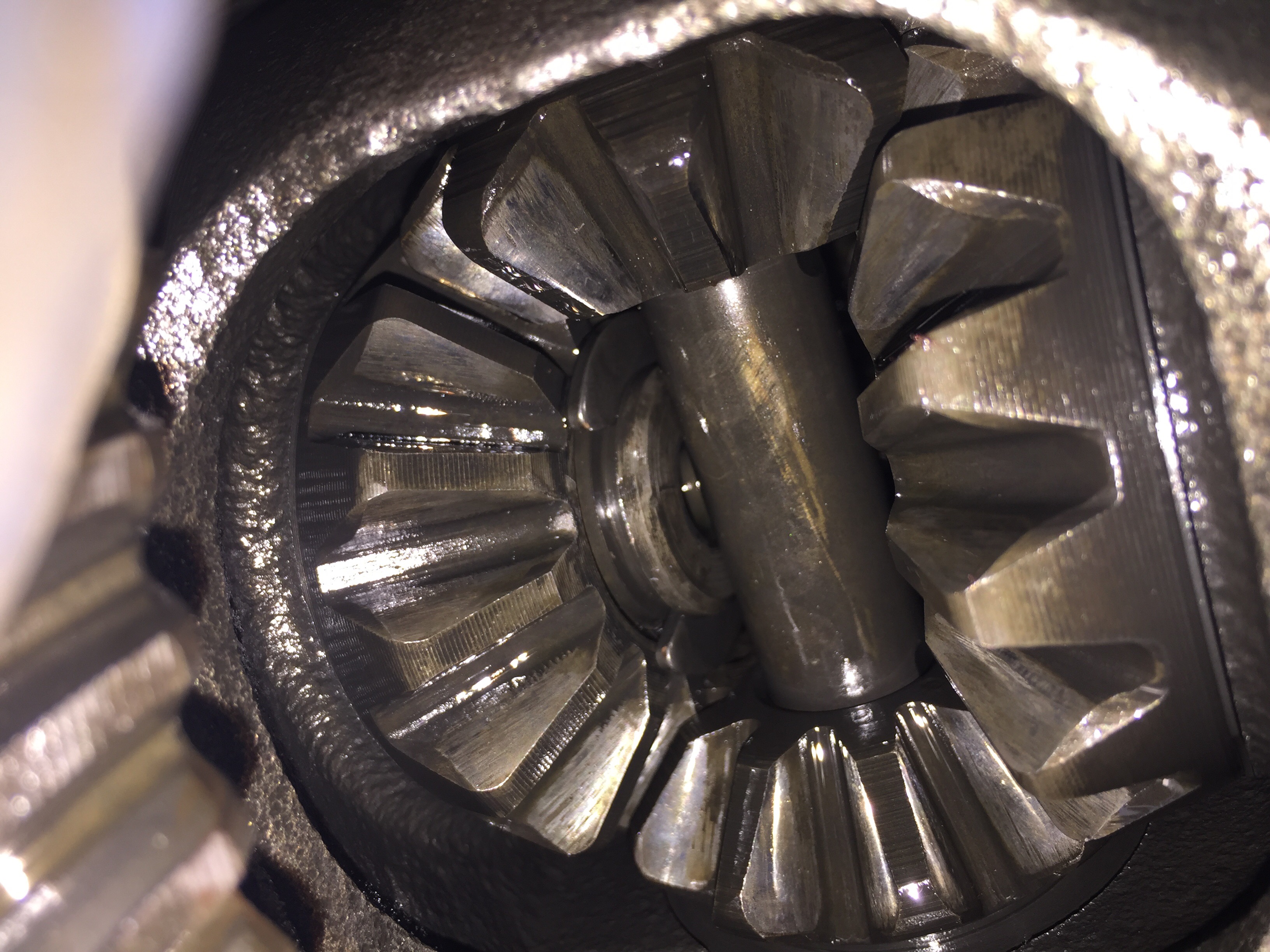
 Once they were clean down enough, I put some anti-seize on the mating surfaces for easier removal next time and slide in the new shafts until they were bottomed out on the spider gear crosspin.

I didn’t remove the inner CAD shaft bearing but made sure to check the clearance when I instal the 1 piece shaft.
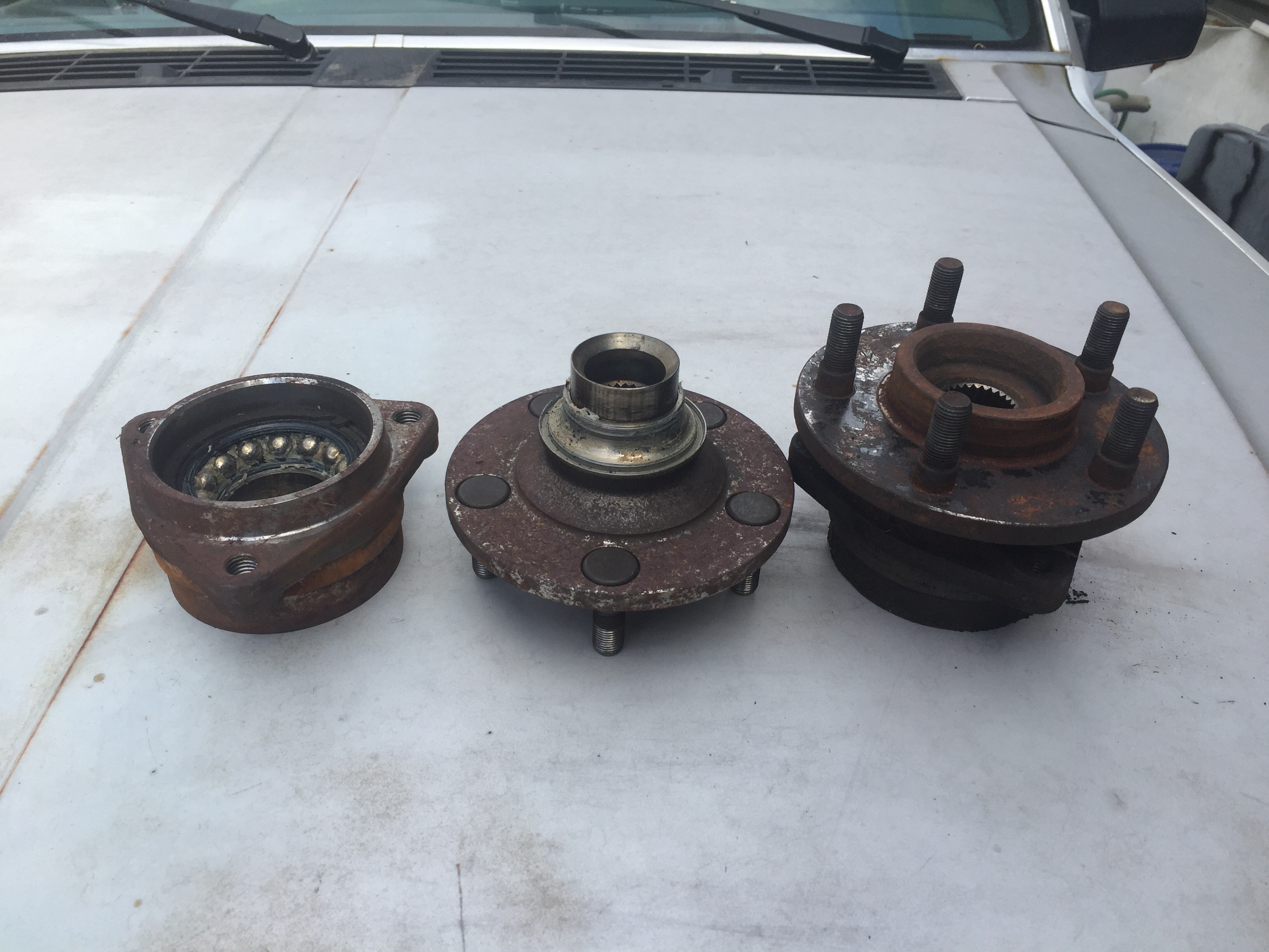
Now to jump off topic for a minute, I purchased new wheel hubs for both side because the driver side hub fell apart once I removed the axle nut. As you’ll notice, Timkin bearings are now made in Korea. Remember I said that for later.

I compared the two old hubs and found out someone had replaced the driver side hub sometime in the past. If you notice in the picture, the broken driver side hub (Left in picture) broke down before the passenger side (Right in the picture) did. Now that could be because the passenger side had the CAD but I don’t think so. If you look at the bearing races when flipped over the driver side (Left) doesn’t say “Timken Made In USA” while the perfectly fine passenger side (Right) does. I don’t know if the passenger side is original from 1987 but it is weird that the Hub made in the USA out lasted the newer non marked hub. To me, it really says a lot about the quality of American made products. It’s sad Timkin is no longer made in the USA.

Since the American made hub was still in good shape, I saved that one as a trail space. So back to the installation. Once the shafts were in on both side, I installed my non-American made Timkin hubs and torqued the mounting bolts to 75ft. Pounds.
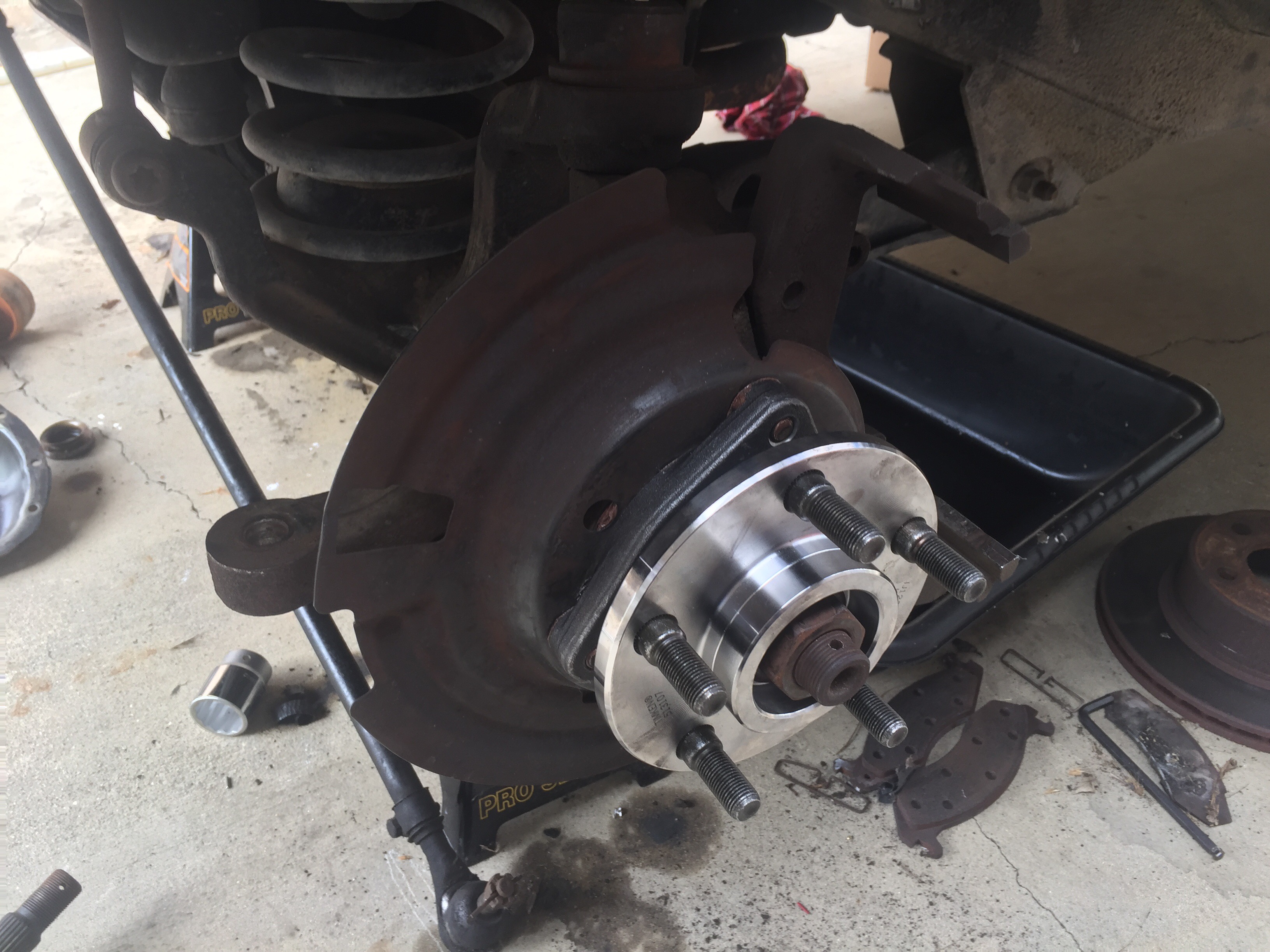

I slide my Axle washer and nut back on and just snugged them up. I’ll torque them down later. I bought new rotors, drums, shoes and pads to ensure the Jeep had plenty of stopping power. I won’t go into detail with the brake job in this article. I’ll discuss a full brake job in a later article.

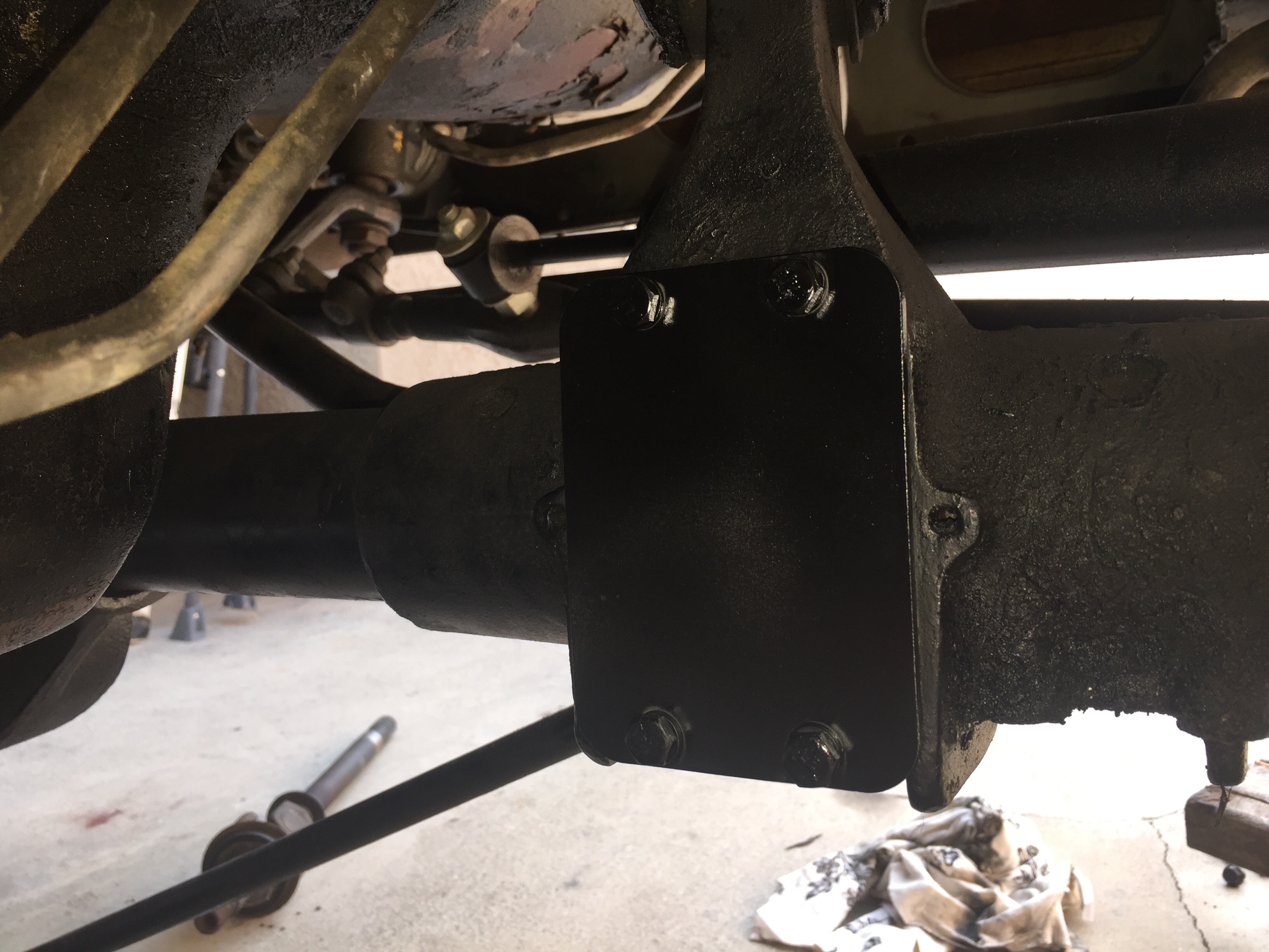
Once I had reassembled the brakes on both sides, I put the finishing touches on the axle. First, I installed the new cover plate from the CAD Delete kit onto the CAD housing where the vacuum motor use to be. I reused the four bolts that held the vacuum cover on.
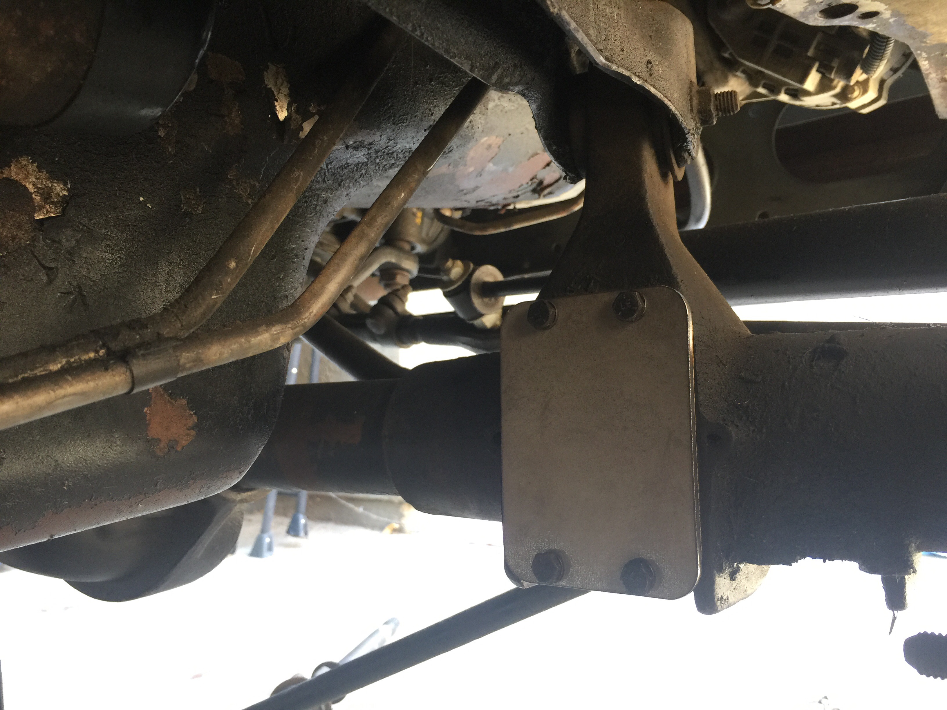
I painted the cover and surrounding area to make the appearance look a little better.
After the new cover plate was on the CAD housing, I cleaned the years of grease and grime off the differential cover and gave it a clean paint job.


I let the paint dry for a bit then put some RTV on the axle housing. It’s a thin coat but looks like I caked it on in the picture. I promise.
I let the RTV tack up for about 10 minutes then installed the differential cover. I torqued the cover down to 30ft. Pounds in a star pattern. Once the cover was on I reinstalled the Tie Rod onto the drivers side.

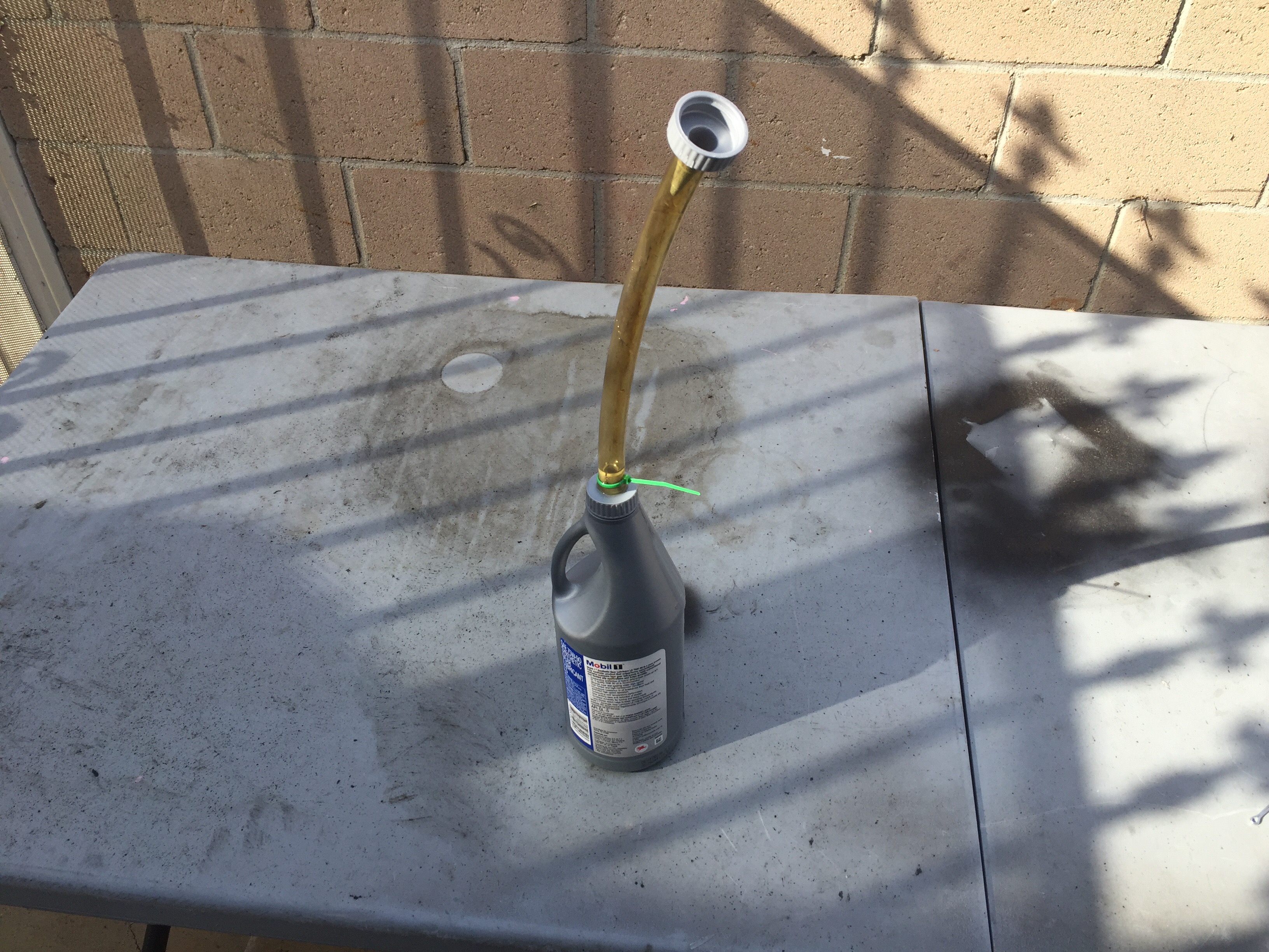
I let the RTV set for 24 Hours before filling the differential with gear oil. I used 75w-90.
After the differential was filled I capped it off and threw the tires back on and snugged them down for now. Once I had jacked the jeep back up to remove the jack stands and set it back on the ground, I torqued the lug nuts to 110ft. Pounds. I then torqued both Axle nuts to 175ft. Pounds. Installed the lock collar and cotter pin and took it for a test drive.
I didn’t notice any noises or binding. I went through all gearing in the transfer case to ensure everything was working as it should. Check back for Dana 30 C.A.D. Delete -Part 3, where I’ll be making the 4×4 light work again.

Hey! I followed your step last year and did this on my 90 cherokee. I used the National 223050 seal and only a year or so later I noticed that its leaking! Behind the CAD delete plate I have oil…. Did yours let go? Is there a better seal to use?
LikeLike
You could use a CR11343 seal but the OD is slightly oversized. We’re talking thousandths of an inch bigger. You could try banging it in but I would recommend freezing the seal over night, then take it out of the freezer just before installing it. To aid you a little more, you could also use a small torch to heat the area the seal will sit on the axle just before you take the frozen seal out to install it. The heat will slightly expand the tube and the freezing of the seal will help shrink it slightly.
LikeLike
I’m about two year into this mod and have seen zero signs of leaking.
LikeLike