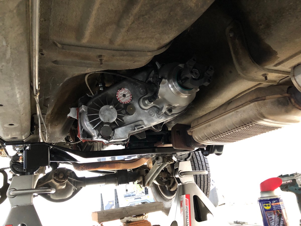
When you lift your XJ more than 3″, most lift manufacturers recommend installing a slip yoke eliminator to avoid losing your driveshaft while off roading, improve driveline angle and help reduce driveline vibrations. On my Cherokee, I chose to go with Advanced Adapters – NP231 Slip Yoke Eliminator Kit. The kit comes with a new 1-3/8″ – 32 spline, rear output shaft, an aluminum tail housing, 1310 C.V. Yoke, required bearings and hardware to get the job done. You don’t have to be an expert to do this job but a few special tools do come in handy when doing this job. While I had my Jeep on jack stands because of my lift being installed, I decided to take a break from all the drilling and heavy work to do some maintenance on my transfer case and also install my new SYE. The first thing to do is to support the transmission with a block of wood spanning the transmission pan on a jack. This was required to remove the crossmember. On some models, you might have a transfer case skid plate that needs to be removed at well. Mine did not have this skid plate. There a four bolts that must be removed first from the transmission mount. Remove these first to take the weight off the crossmember when you lift the jack slightly. Once the jack was supporting everything, I removed the two bolts and nuts from the studs on each side of the unibody rails and dropped the crossmember.  Set the crossmember aside with the bolts and nuts you removed from it. In my case, I was installing a long arm kit that came with a new crossmember, skid plate and mounting hardware so I just discarded mine.
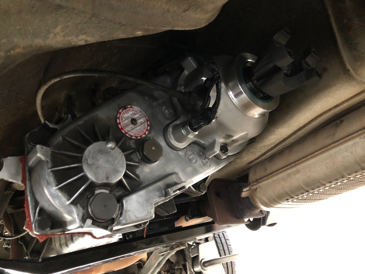
  With the crossmember out of the way, I disconnected the transfer case shift linkage. I used a screw driver to pry the linkage from its connecting point on the transfer case. I’m also installing a Boostwerks Engineering HD shift linkage kit, so I removed the stock linkage entirely from under the Jeep. With the linkage removed, I lowered the jack holding the transmission and transfer case down to access the top nuts that couple the transfer case to the transmission. There were six nuts total that need to be removed around the transfer case. Before removing the transfer case, I unplugged the electrical connector for the shift indicator and unscrewed the speedometer cable going into the transfer case. Lastly, there is a vent hose on the top side of the case that need to be removed. Once all these are disconnected and the case is unbolted, I lifted the case and pulled the transfer case out.
 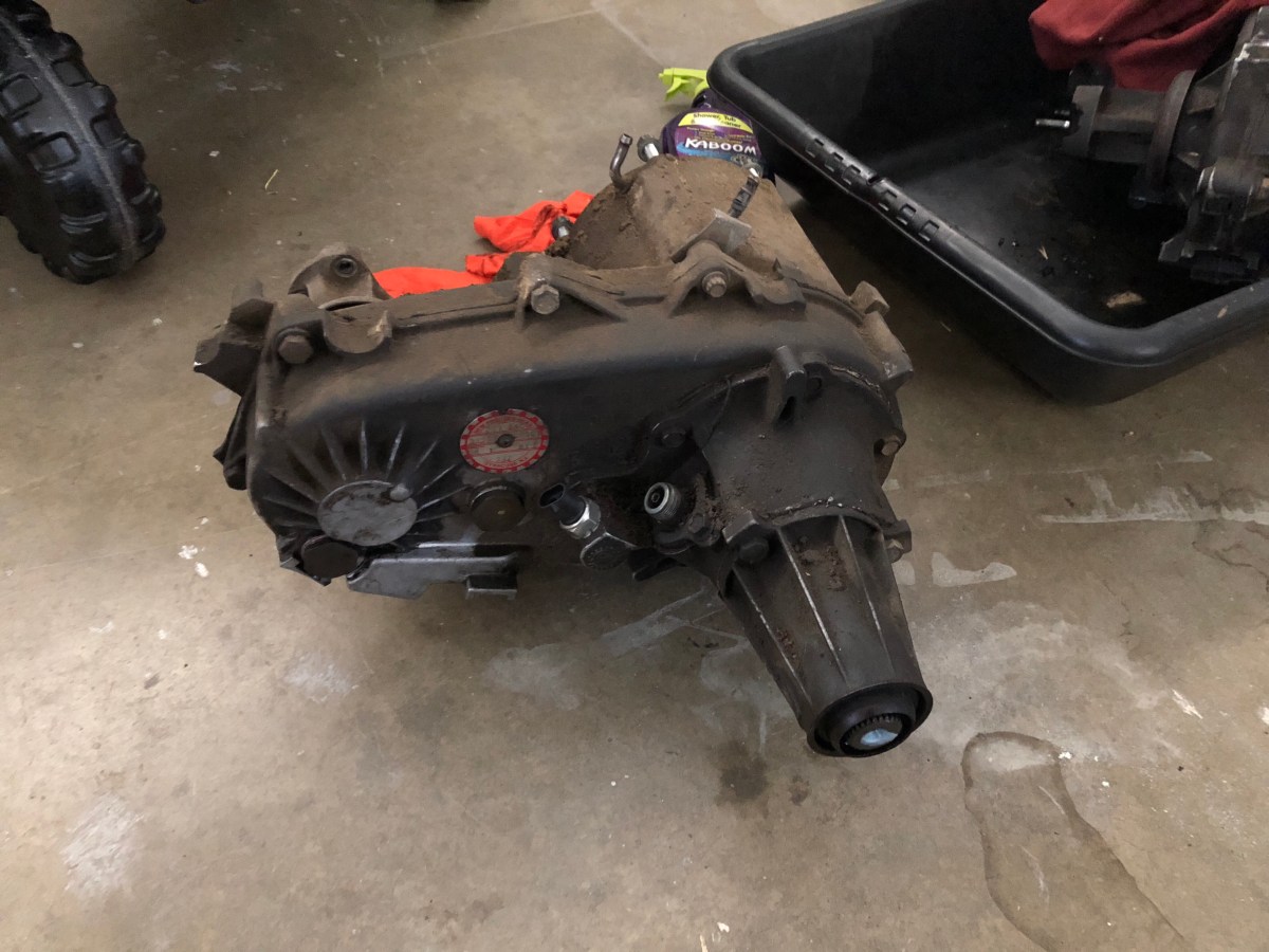 With the case out, I jacked the transmission back up and supported it with a 2×4.
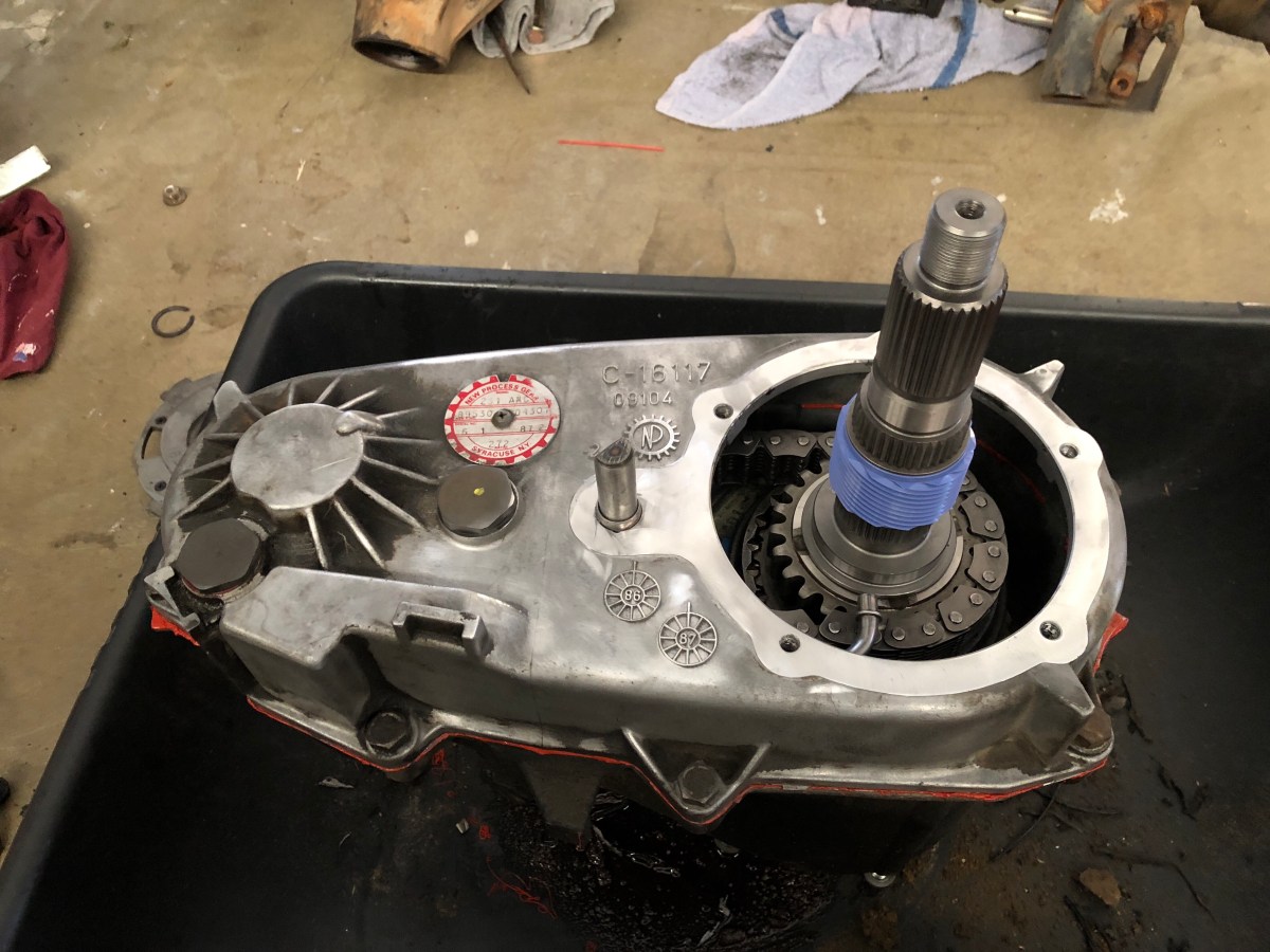
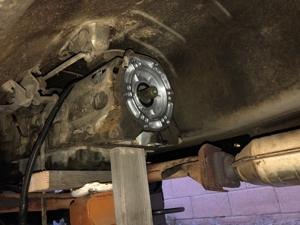 First step in the SYE swap was to remove the nut and front yoke. I used an 1-1/8″ socket to remove the nut then slid the yoke off.
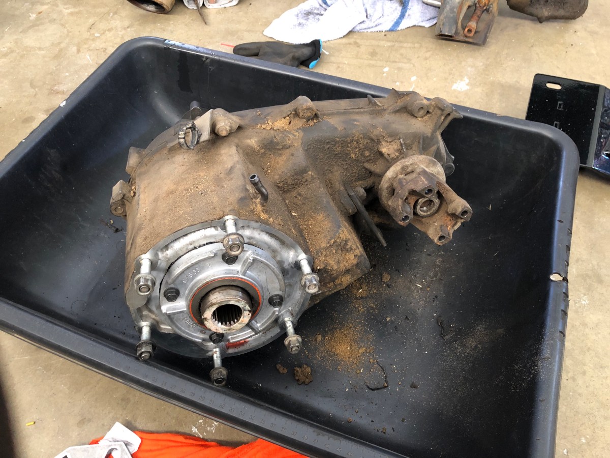
 Having the front yoke off allowed me to pull the guts of the transfer case out later. Next, I removed the speedometer drive gear from the old housing.
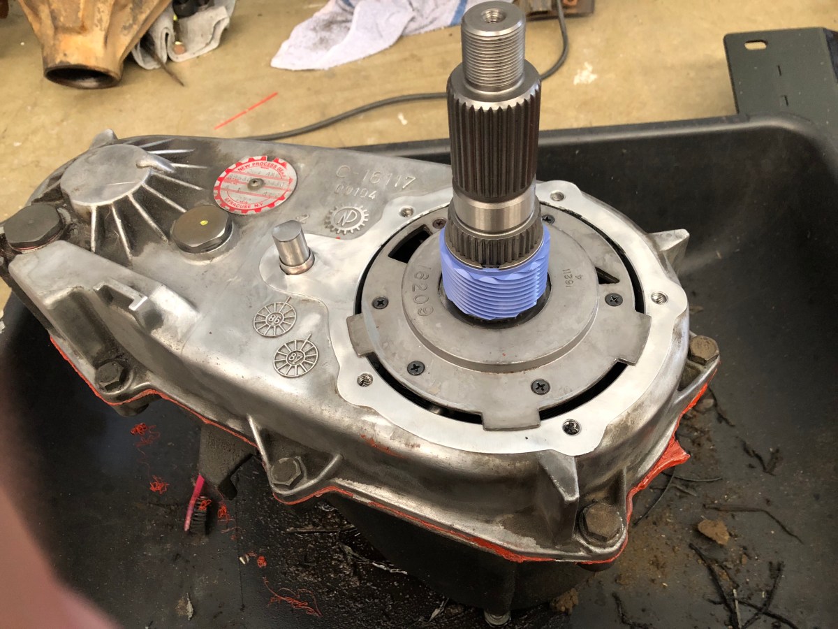
  With the speedometer gear removed, I could remove the tail housing from the case. I removed the rear output shaft cover first. There were three bolts holding it on. After removing them, I discarded the bolts and the cover.
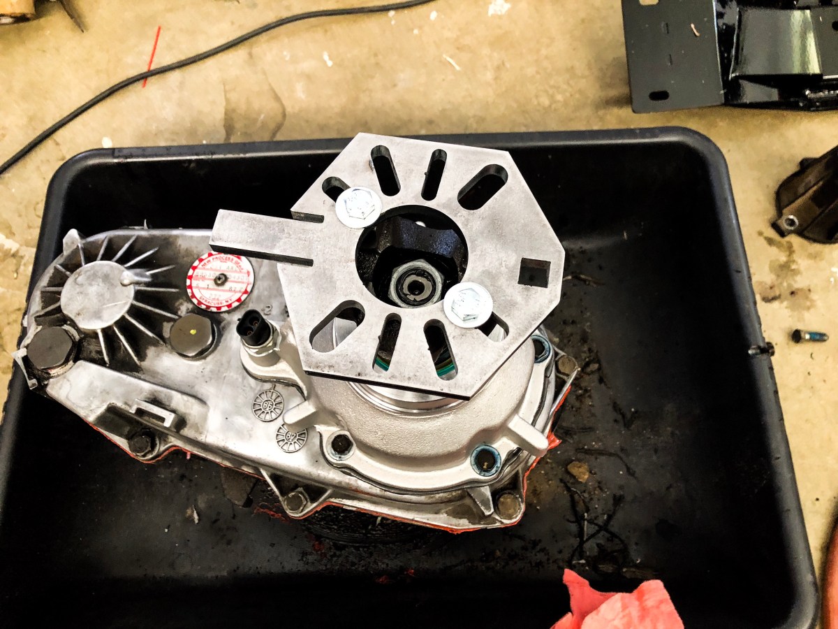
 Before removing the tail housing, I had to remove a snap ring that held the rear bearing in the tail housing. I modified a set of snap ring pliers by heating them and bending the to a 45° angle to better aid in removing the snap rings throughout the installation. With the snap ring off, some gentle taps with a dead blow hammer broke the silicone seal that was made between the case and the tail housing.
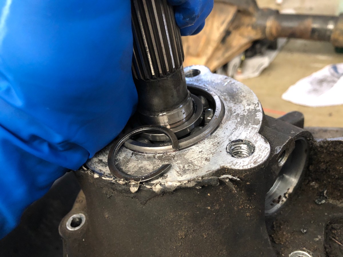
 With the tail housing remove, the oil pump is exposed. There was no snap ring holding the pump on the old shaft but there is the oil pump pickup tube that needs to be removed from the pump before it would lift off. I used a small screw driver to gently pry it out of the pump. Once the pickup tube was out, I could lift the pump off the shaft. The tube has a small o-ring that fits inside the pump that didn’t come out when I pulled the tube. I fished it out of the pump with a small pick and slide it back over the tube as to not lose it during the installation of the pump on the new shaft.
  Now that the inners of the case are exposed, I could now remove the the rear half of the case. There were eight bolts that I had to remove but there is one bolt that is different from the other case bolts. I made note of where that bolt went and proceeded to remove all the other bolts. On the side of the case, there were small pry point where a screwdriver could fit and aid in separating the two halves. It took some force to break the silicone seal but it eventually came free and I removed the back of the case housing.
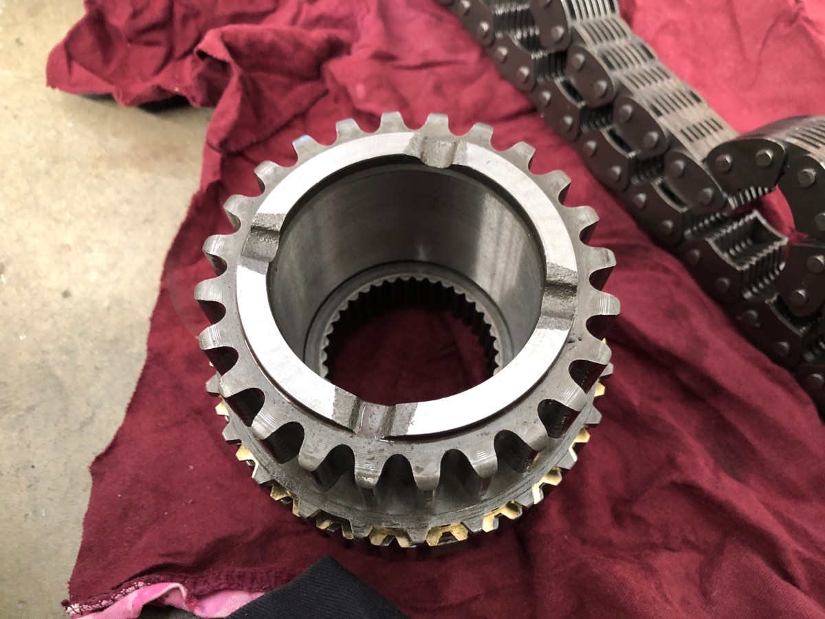
  With the case split, I lifted the rear shaft and front shaft out of the case. It took some jiggling but it eventually lifted out, chain and all. I had to remove the mode hub assembly from the old shaft. There is a snap ring in the back of the output shaft that needed to be removed. Once removed, the mode hub slid off the old shaft.
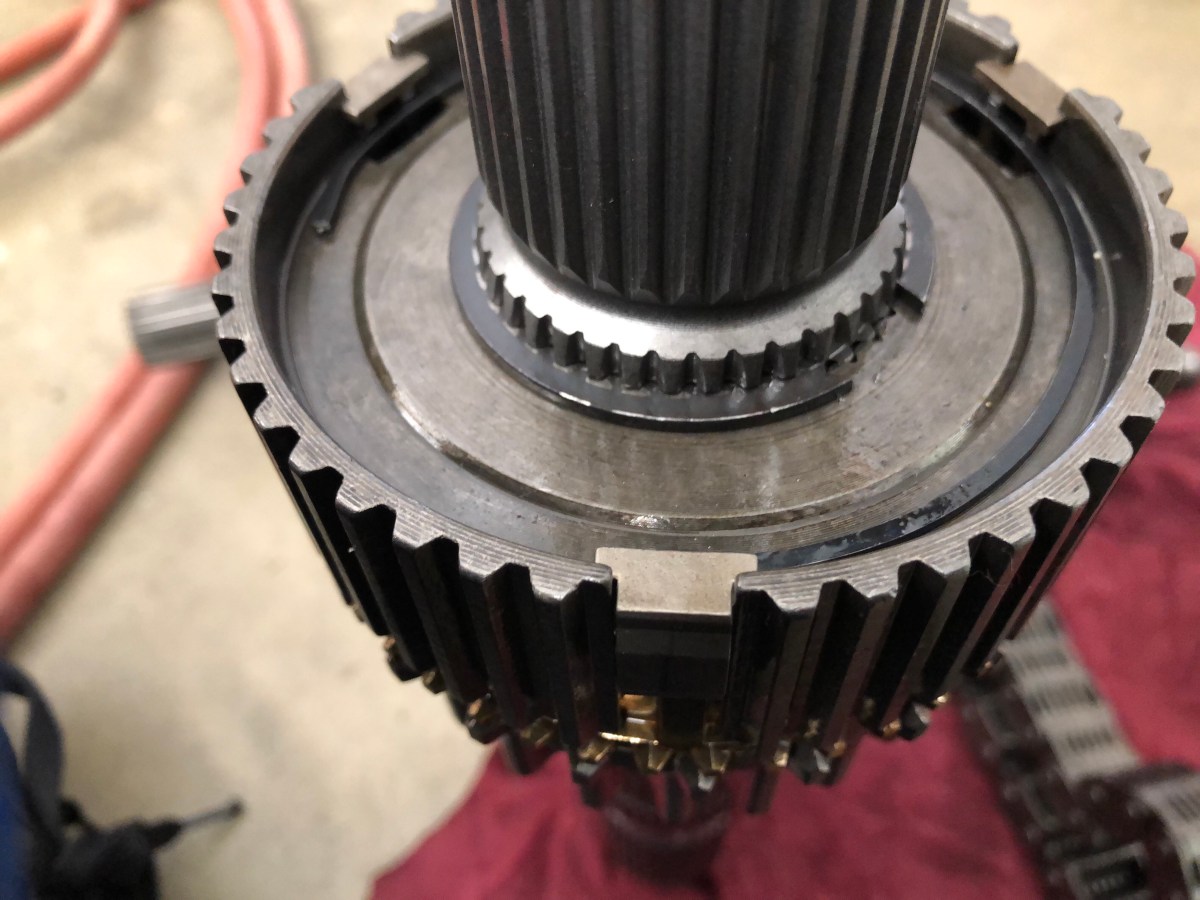
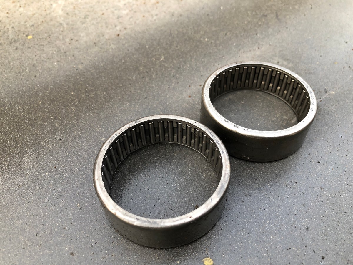
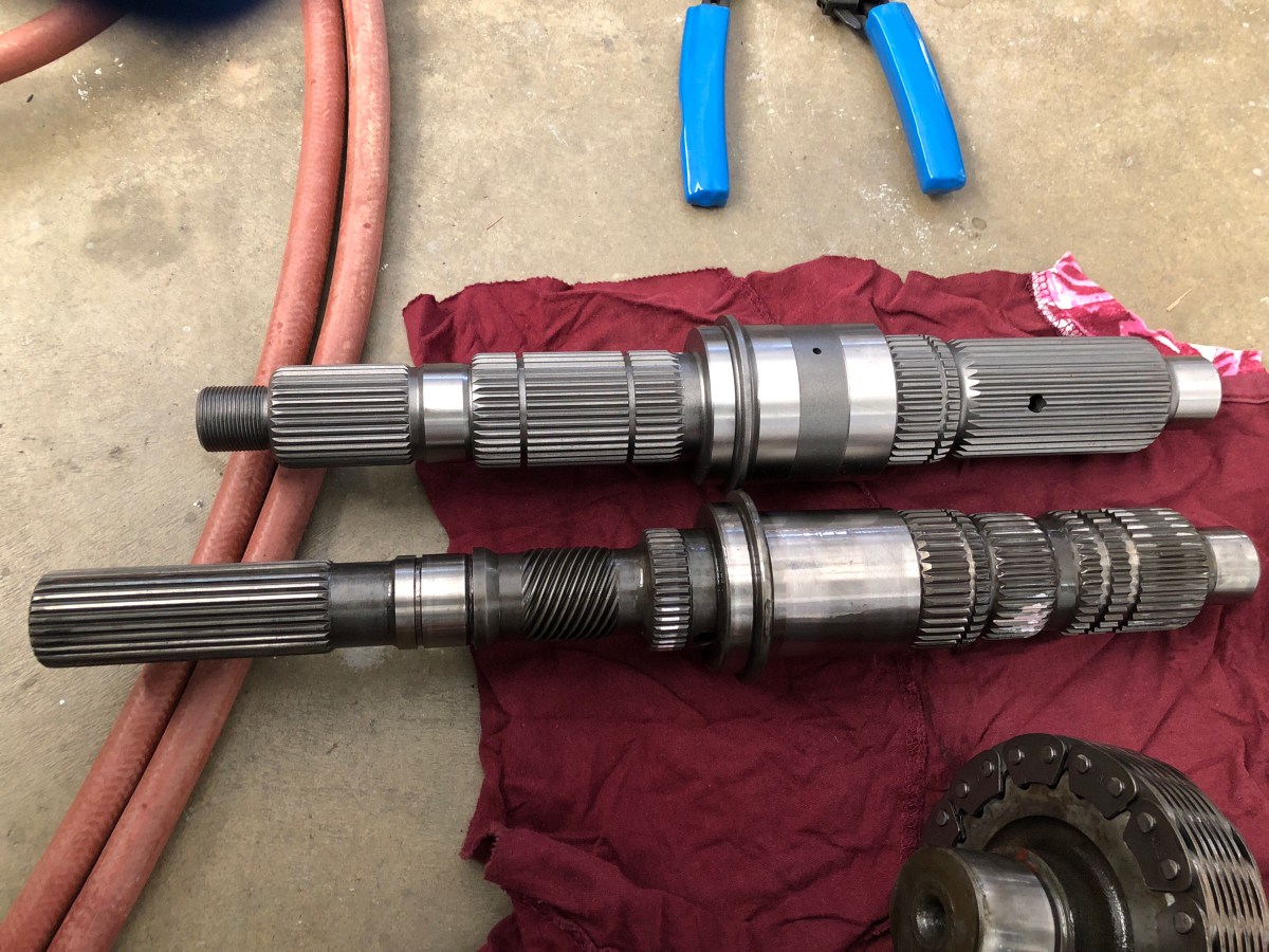
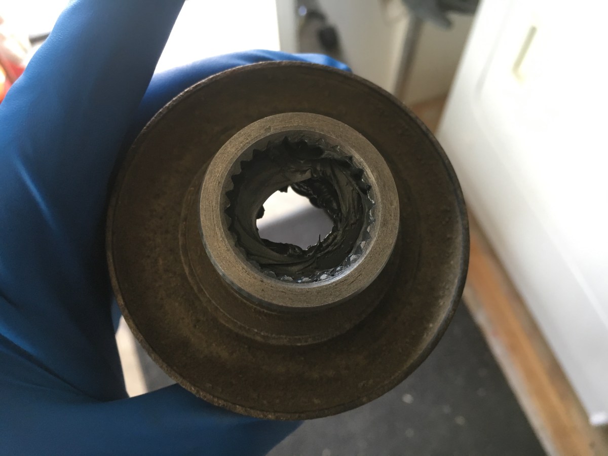
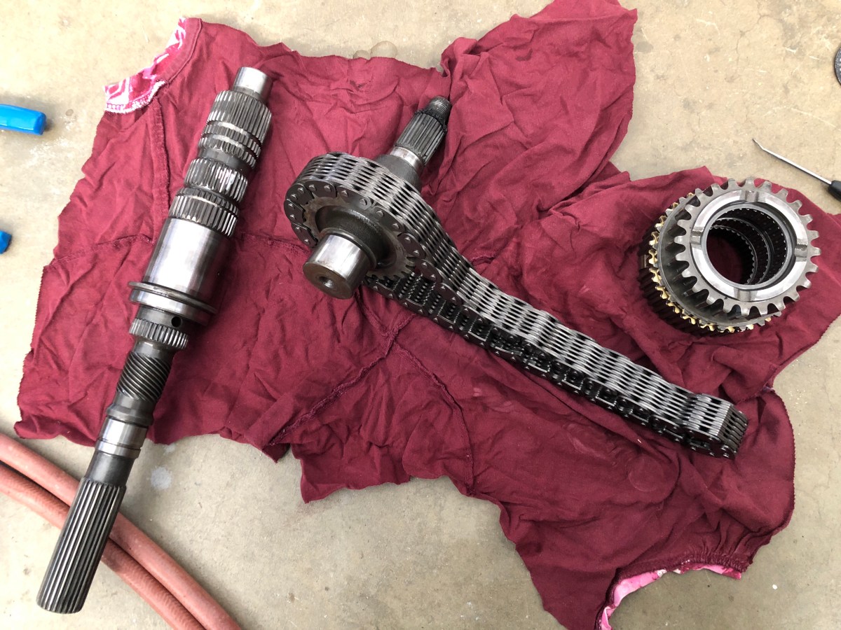 On older output shaft, the mode hub has two sets of needle bearings that needed to be removed. I used the new shaft to press out the needle bearings from the mode hub. Here is also a picture of the old shaft and new shaft side by side.
 With the old needle bearings out, I could now start the rebuilding process. I basically put it back together in the reverse order. I started with the mode hub onto the new shaft. I slid it on and installed the old snap ring back on.
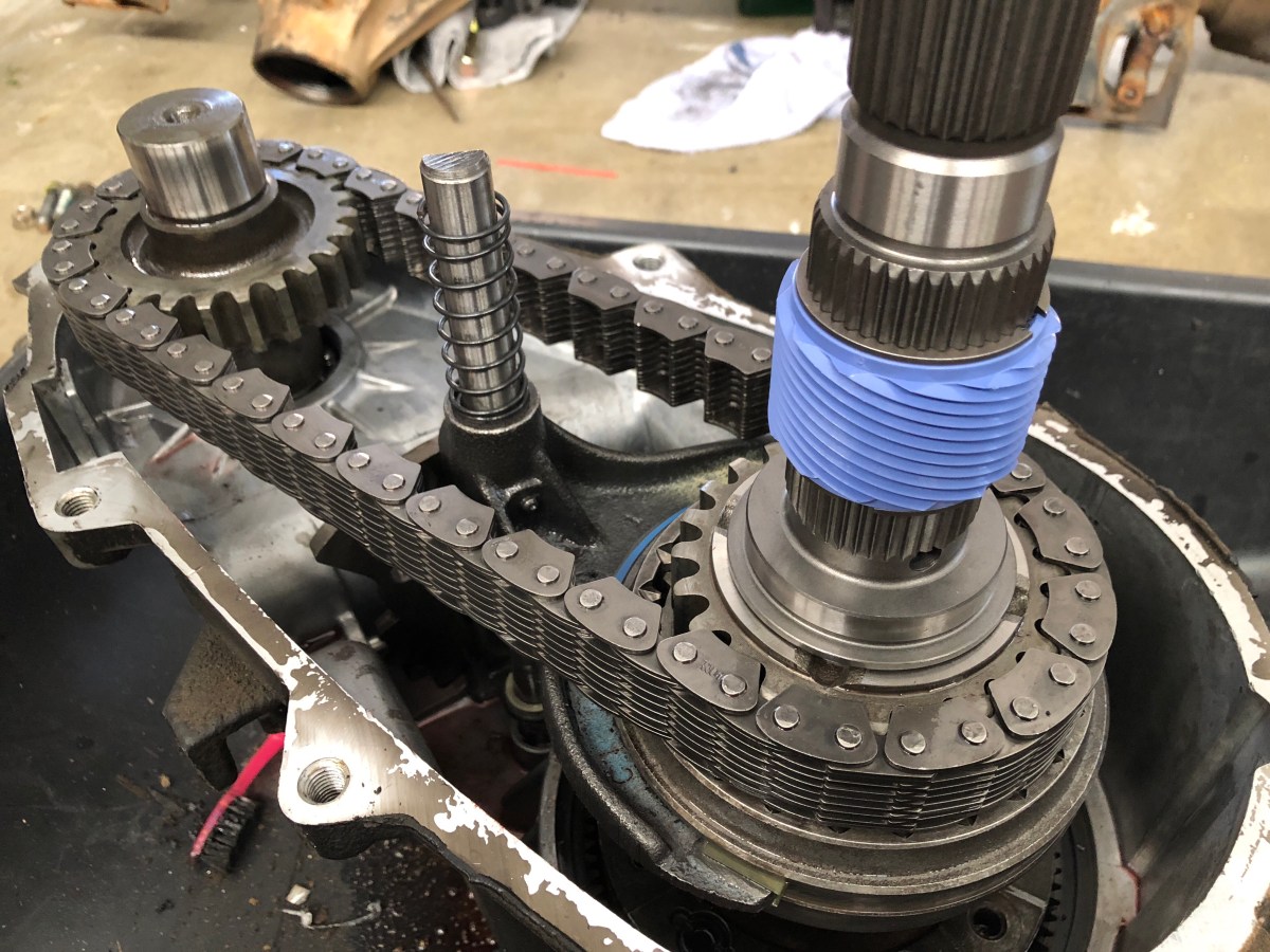
 With the mode selector back on, I put the new shaft back in the chain and gently reinstalled it back into the case as one unit. In the next few photos, you’ll see where I messed up and installed the speedometer gear collar prematurely. That collar should be installed after the oil pump is reinstalled.
Once the shafts were slid back in the case, I covered all the inner components of the case and used a razor blade clean the old silicone off the case matting surfaces. I cleaned the magnet that’s also inside the case and reinstalled it.

With the oil pump tube and filter reinstalled, I put a nice bead of silicone on the the rear half of the case and slid it back on the front half of the case. I installed and snugged the bolts down until the silicone set a little then torqued them down to spec.
Before I installed the oil pump, I had to cut down the shift indicator shaft. I planned on using the stock transfer case selector switch so the shaft had to be cut down to stick out one inch in 4Low. Once I had my mark on the shaft, I used a cut off wheel to chop it down.


With the shaft cut down, I slid the oil pump onto the output shaft. I used a small pick to slide the oil pump pickup tube back into the oil pump (hard to see but in the red circle).

In the kit Advanced Adapters sends you, there will be two new snap rings. The first snap ring goes on after the oil pump is installed and it holds the oil pump in place. Next I slid the speedometer gear collar onto the new shaft and installed the second snap ring to hold it in place.

With the case assembled to this point, I could finally install the new tail housing Advanced Adapters sent with the kit. I put a thin bead of silicone on to the new housing and let it sit for about 20 minutes to slightly cure before installing it. After it cured slightly, I slid it over the output shaft and made sure it was lined up with the selector shaft while installing. I used some blue lock-tite on the mounting bolts and torqued them down to spec.


With the tail housing installed and torqued down, I installed the selector switch and reinstalled the speedometer gear assembly. The speedometer gear assembly is marked so you can adjust it once it’s installed so the gears line up properly. All I did was line it up with the retaining bracket mounting hole. I believe the stock one I have was a 34 tooth count.

I let the case sit overnight to let the silicone cure fully before installing the yokes. The kit comes with two new star washers that go inside the yokes to seal the splines so they don’t leak out out. Before I slide the new star washers in, I put a liberal amount of silicone inside the yoke to aid in sealing the splines.
I did one yoke at a time but started with the rear yoke. After I siliconed the inner splines of the yoke, I put some lube on the tail housing seal so the outside of the yoke didn’t damage the seal. I slid the yoke on the rear output shaft and ran the new yoke nut on. I used my handy dandy BleepinJeep Yoke Tool to aid in torquing the yoke nut down to 145 foot pounds. I did the same thing on the front yoke when I was done with the rear.

I cycled through all the ranges of the case and made sure everything was functioning properly. Before installing the case back into the Jeep I swapped out the shifter linkage bracket for the new Boostwerks Engineering bracket.

All that was left at this point was to install the case back onto the transmission and bolt it down. I installed a new transmission mount before installing the new crossmember just because I didn’t know the last time it was changed and it was only $15.00. With the crossmember holding the weight of the transmission and transfer case, I hooked up the speedometer cable, vent tube and selector switch connector. All that was left was to wait for my new driveshaft to come in the mail and install it. Making sure my driveline angle is correct to prevent vibrations while driving.