Anyone that has owned a Renix era Jeep knows the closed loop cooling system isn’t the best and can be a pain to maintain. In an earlier write up, I explained how I upgraded the cooling system from a closed loop system to an open system. The swap was pretty simple but when it came to mounting the ‘91 and newer overflow bottle, I had no clue where to mount it. The factory location required the factory ‘91+ fuse box and brackets which I didn’t have. Another way was following the BleepinJeep way and make a custom bracket like Matt did on his Zombie Jeep Build. I chose the custom bracket method but in the factory location which I’ll show in a later write up.
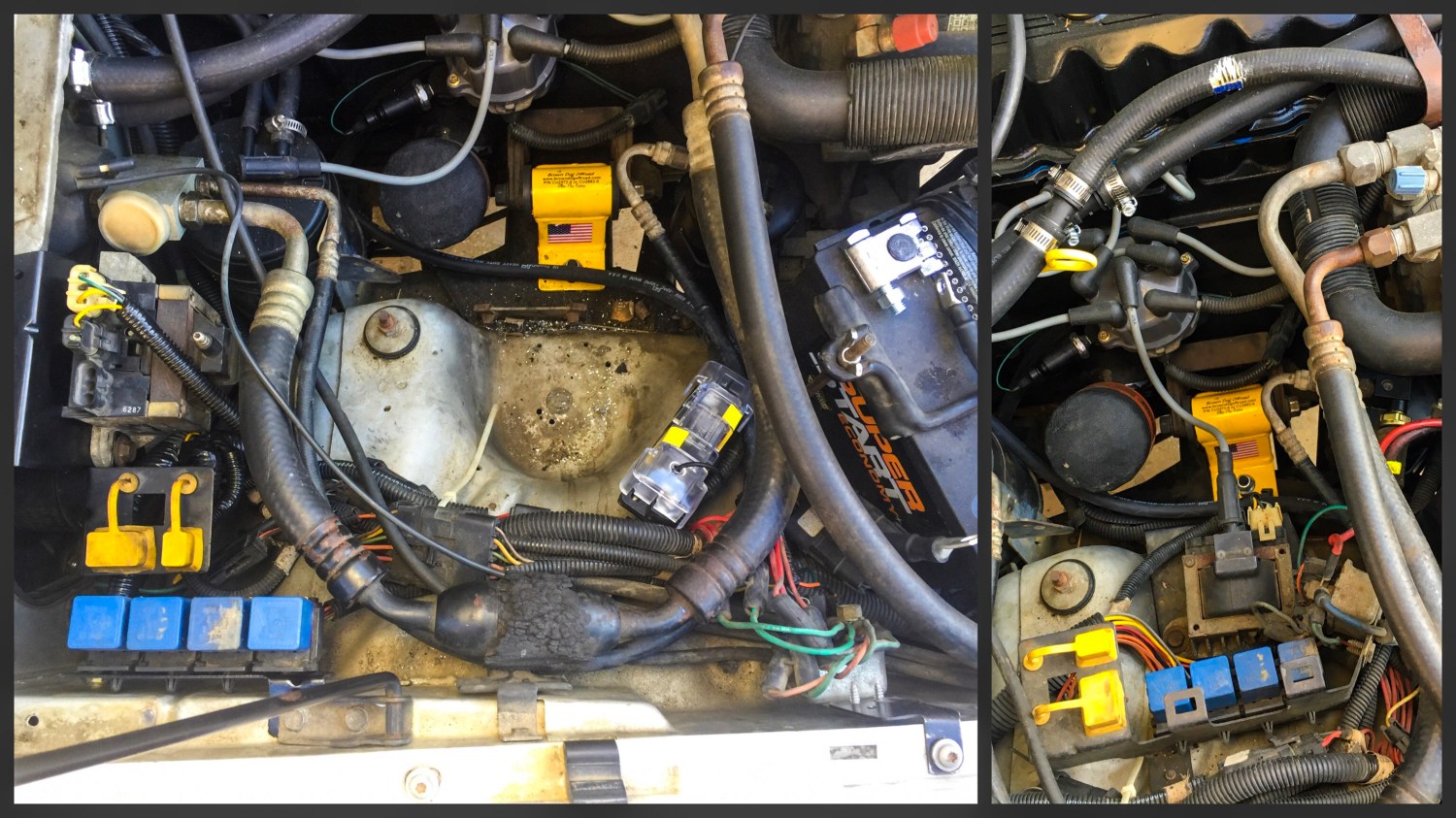
In this write up I wanted to clean up the wiring mess under the hood on the passenger side wheel-well while making room for overflow bottle for nearly ZERO DOLLARS. I decided the only way to get the overflow bottle in the factory location was to relocate all the components that were in its place when AMC was running the show. First, a look at what needed to be moved.

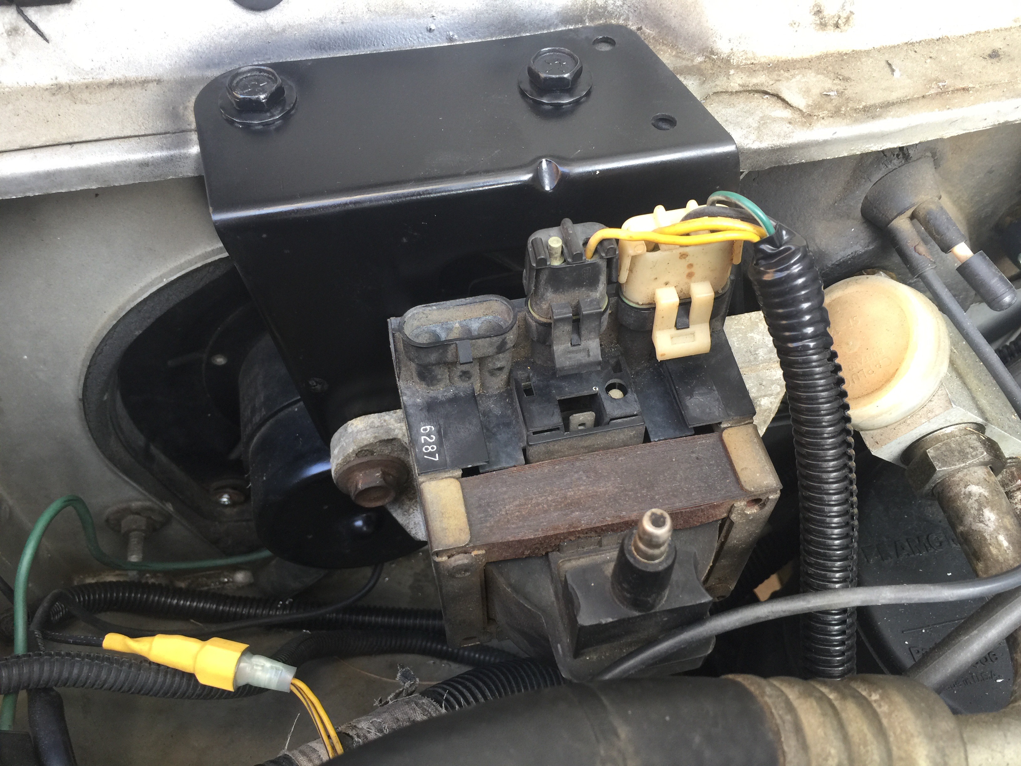
The first thing I noticed was the Ignition Coil, Ignition Control Module, and its bracket were sitting right where the bottle was suppose to be. To remove the ICM and Coil, I first removed the two plugs from the ICM and the Coil wire, then the two bolts at the back of the ICM that hold it down.
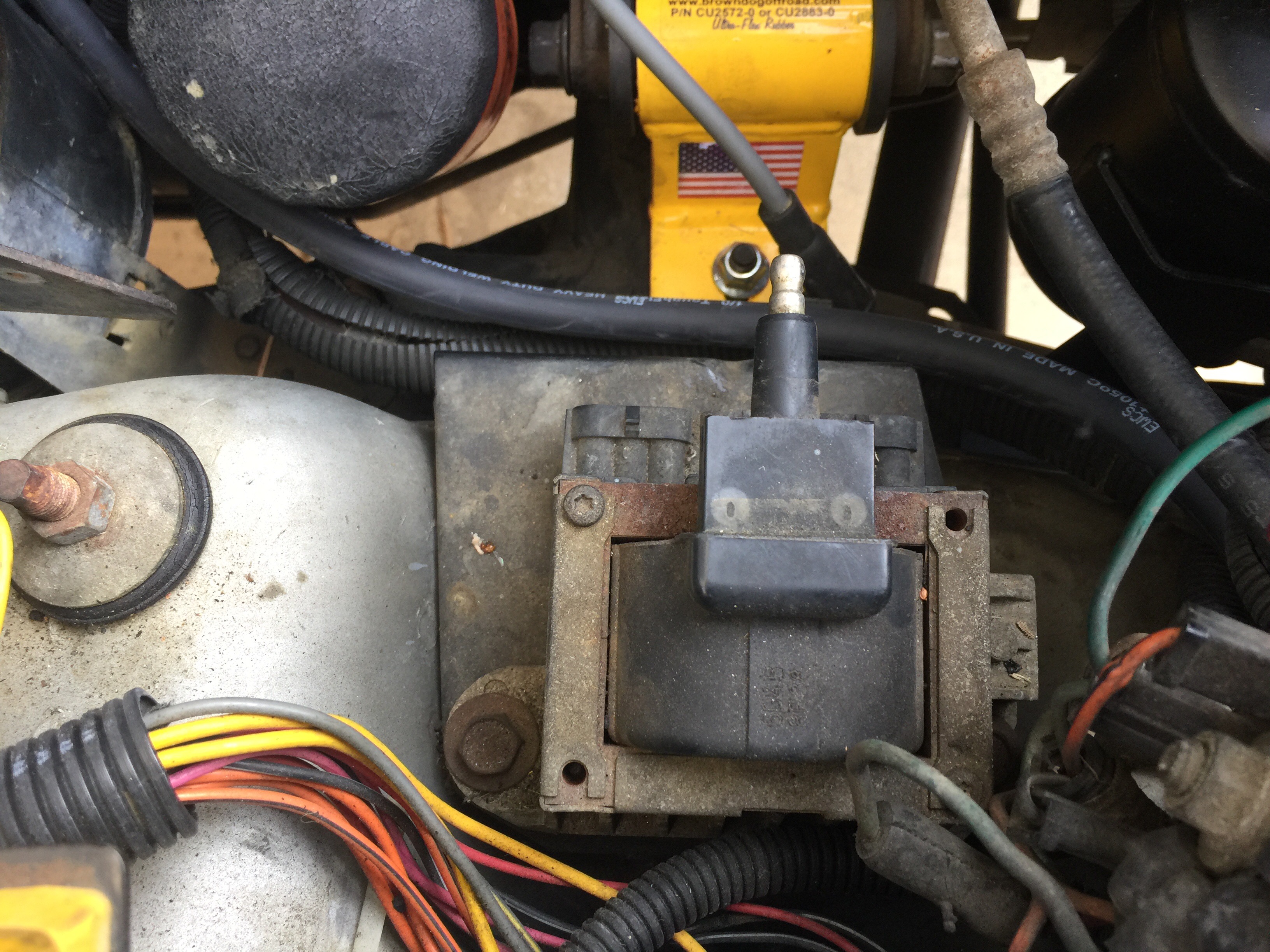
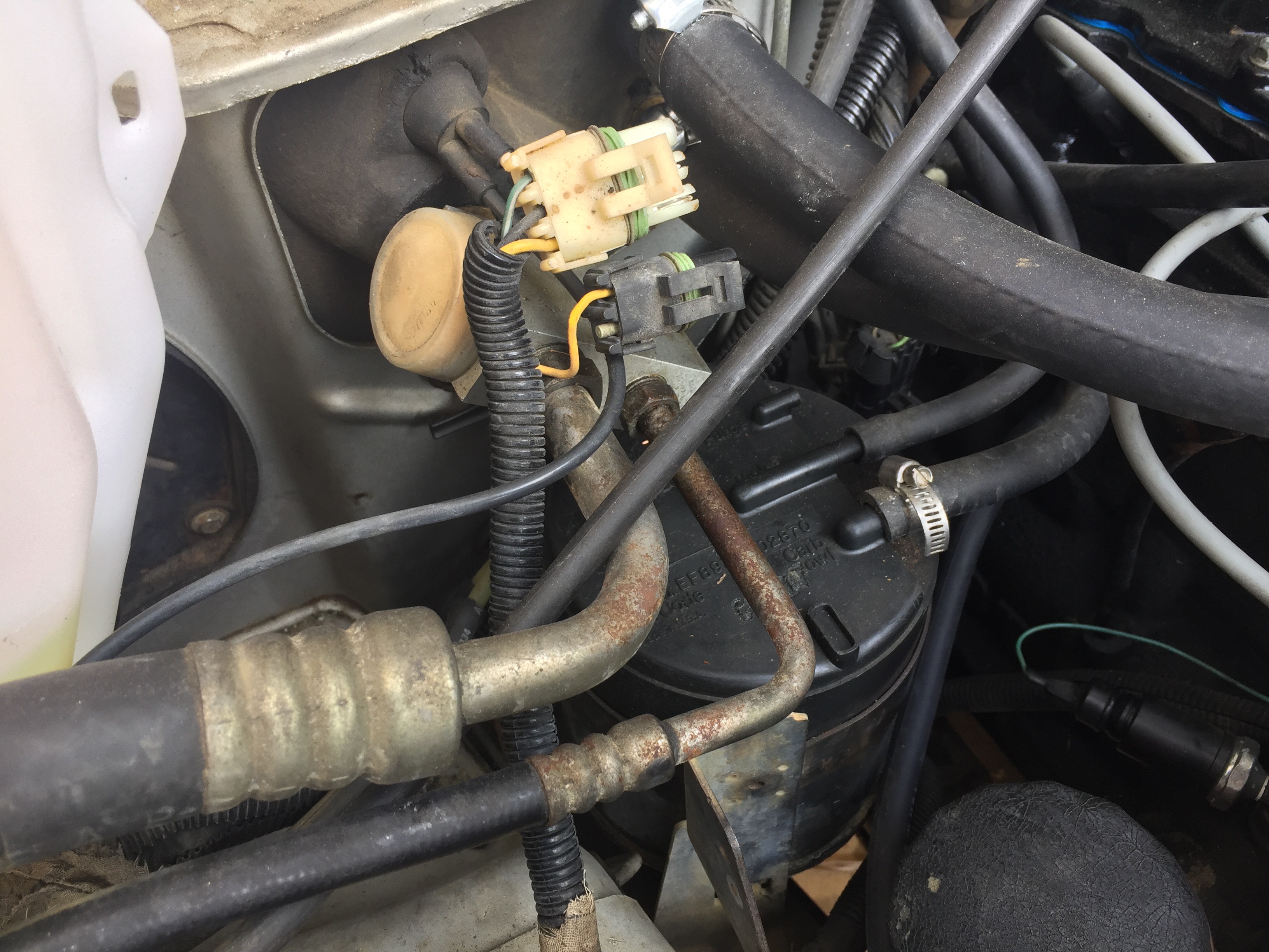
To remove the bracket, there are three additional bolts to remove. Two on the front near the motor mount and one screw under the ICM on a stand-off bracket. Once the bolts are out you can lift the the bracket out. I pulled the plugs near the firewall to see how much room I had to move the bracket.
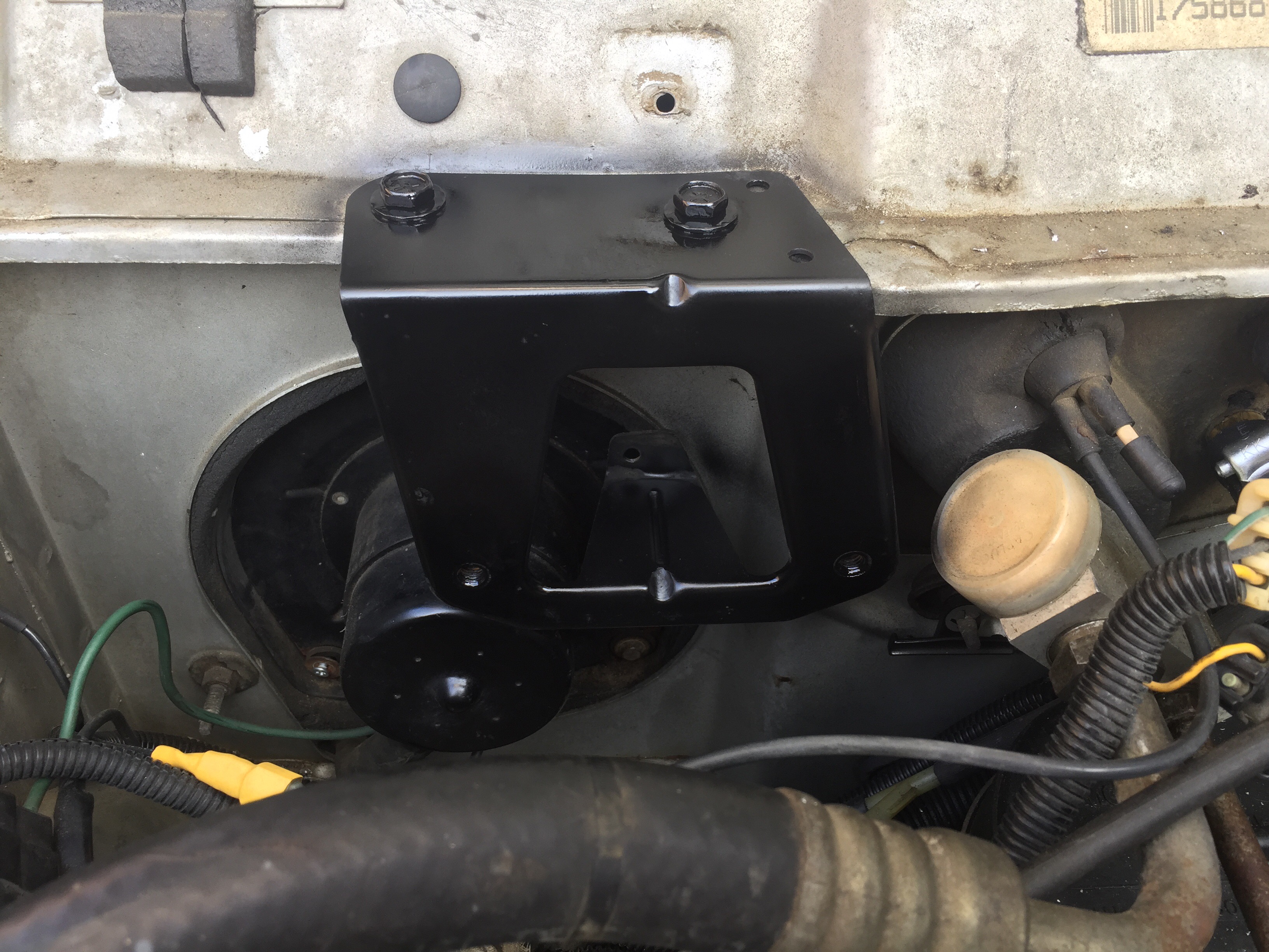
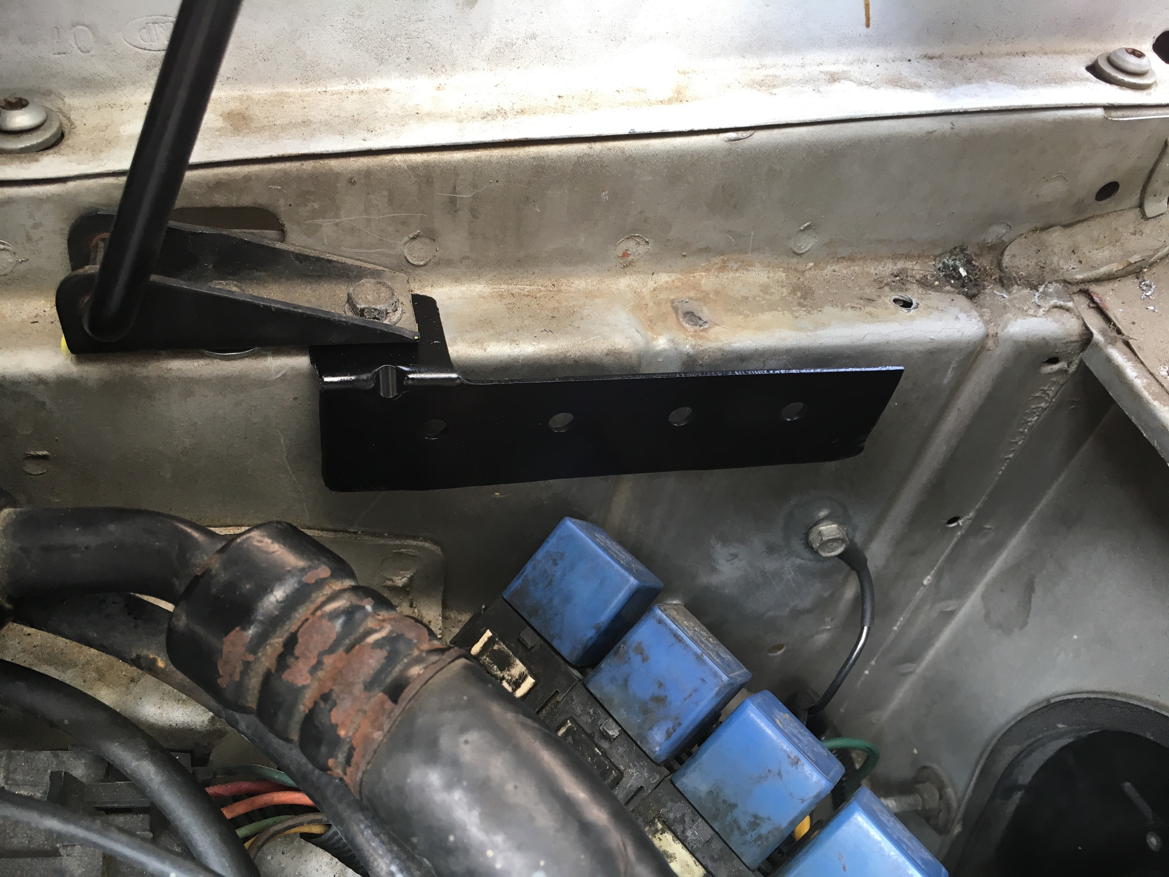
I found the best place to mount the bracket was in the pinch seam near the AC blower motor. The stand-off on the bracket sits perfectly against the firewall. I marked the pinch seam where the original bracket holes are and drilled and tapped the holes to 5/16 standard threads. I gave the bracket a fresh paint job and mounted it up.
I bolted the ICM and Coil to the bracket and verified the ICM plugs would reach. Perfect fit. I just need to get a longer coil wire, but I’ll be putting custom spark plug wires on in the near future. This is where the nearly zero dollars comes in. A longer, pre-made, replacement coil wire can be acquired from AutoZone for $7.99 or a build your own kit can be bought on eBay for $5.00.
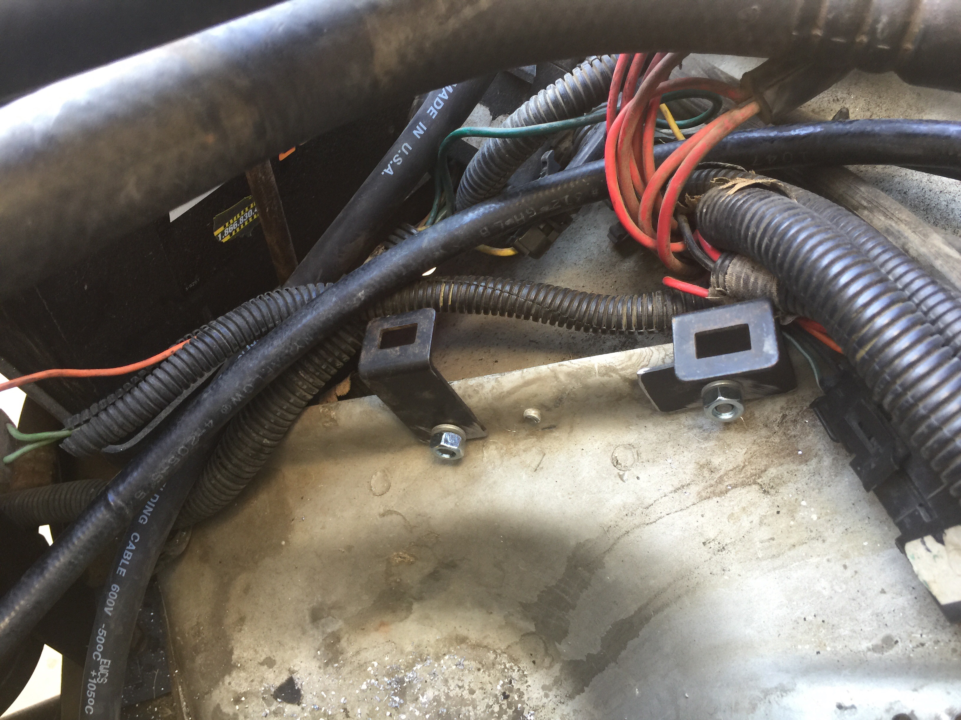
Next it was time to relocate the data ports, the four relays and ignition relay. To remove the data ports from the bracket, simply pinch the sides of each connector and slide one side of the connectors out at a time. Move the connectors to the side. Next are the four relays on the bracket. There are four clips on the back of the of the bracket that look like arrowheads. I just pinched the two wings of each arrowhead together and pulled them out of the bracket.
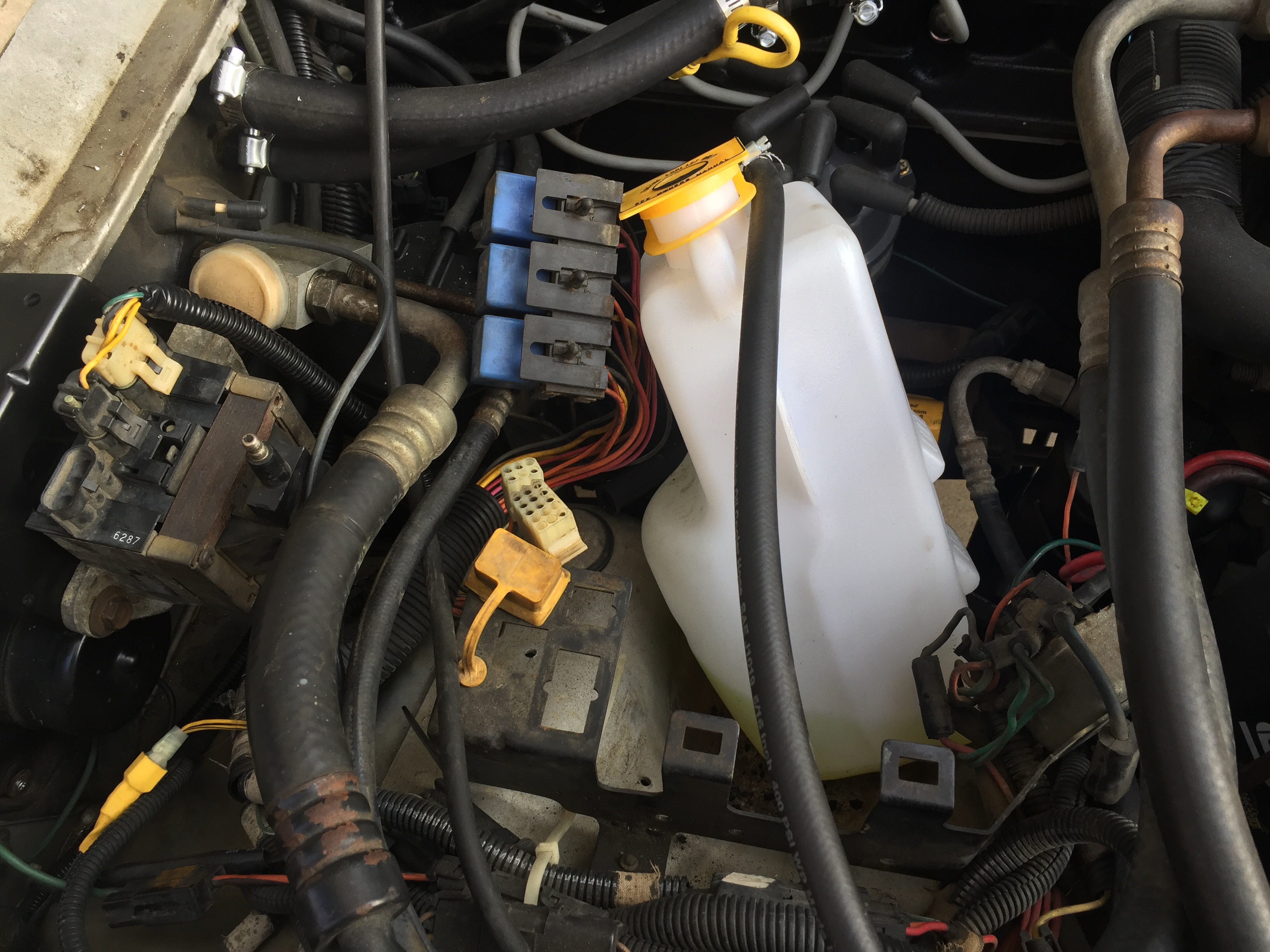
Lastly, I removed the Ignition Relay from the bracket. Simply remove the two screws that hold it on to the bracket. Now it was time to remove the bracket from the wheel-well. There are two rivers holding it on that I had to drill out. The first one need to be drilled out from the under the wheel-well. The second is on the pinch seam near the battery tray. I drilled those out and used some pliers to remove the river heads. Now the old bracket can come out but don’t discard it. Your going to have to chop it up with a grinder and cut off wheel so you can relocate every component and you will use EVERY piece of that old bracket.
Here is a photo of how I cut my bracket up. Again, you will use EVERY piece of this bracket so don’t mess up too bad when you chop it up.

Once the bracket was chopped up, I started with the relays first. The mounting tab on the bracketthats at a 45° angle needs to be bent to a 90° angle. Once the tab is bent give it a shot of paint. I loosen the bolts for the hood prop an slid the relay mounting tab under it ad bolted the hood prop back down wth the bracket under it.
The relays slide apart from each other so take the relay that was on the far left and reposition it to the far right side to give the wiring for that relay some slack. Once you confirmed all the wiring has slack. Install some new split loom on the exposed wires and toe the looms on each end. After that, I pushed the relays back into the mounting bracket.
Next is the data ports. The mount is at a slight angle and will need to be hammered straight. Once it’s straight, give the bracket a quick paint job then remove the left hand (passenger side) bolt that hold the ICM to the ICM mounting bracket. Some grinding one the data port mount is needed to make the data port bracket tab hole line up with the ICM mounting hole. Once the holes line up, reinstall the ICM mounting bolt through the data port bracket and plug the data plugs back in the bottom of the bracket. This is how it should look once it’s all back together.

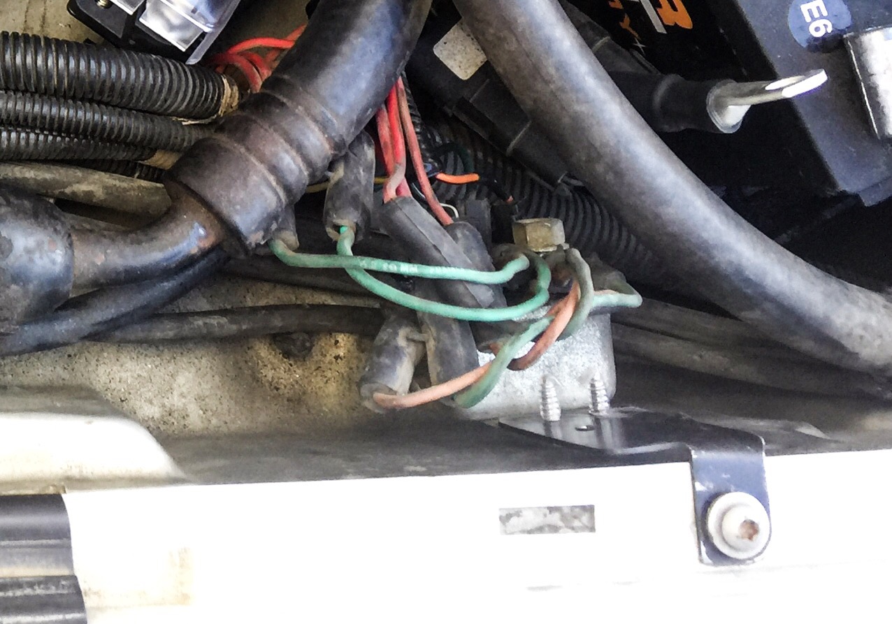
Lastly is the Ignition relay mount. I used the hole that the rivet use to be in. I bent the small tab at a 90° angle and grinder the end of it down for clearance when I mounted it. I used one of the fender bolts as my mount for the bracket. Before you bolt it down, secure the ignition relay to the mounting bracket first then bolt the bracket to the fender. I put some clear heat shrink over the mounting screw just for insulation in case one of the fusible links ever made contact with the the screws.
Hook all your wires back up and enjoy the newly acquired space in the engine compartment that cost you nearly ZERO dollars. Now I know your thinking “Hey, you said I’d use EVERY piece of that old bracket?” Well that was true, to a point. This is where I give you an advertisement for one of the items that will be coming soon to the RenixAaron Store. In a later write up I’ll be showing you how to I install our “Heavyweight Battery Cable Kit” for single and dual battery setups in 2AWG, 1/0AWG and 2/0AWG wire sizes.
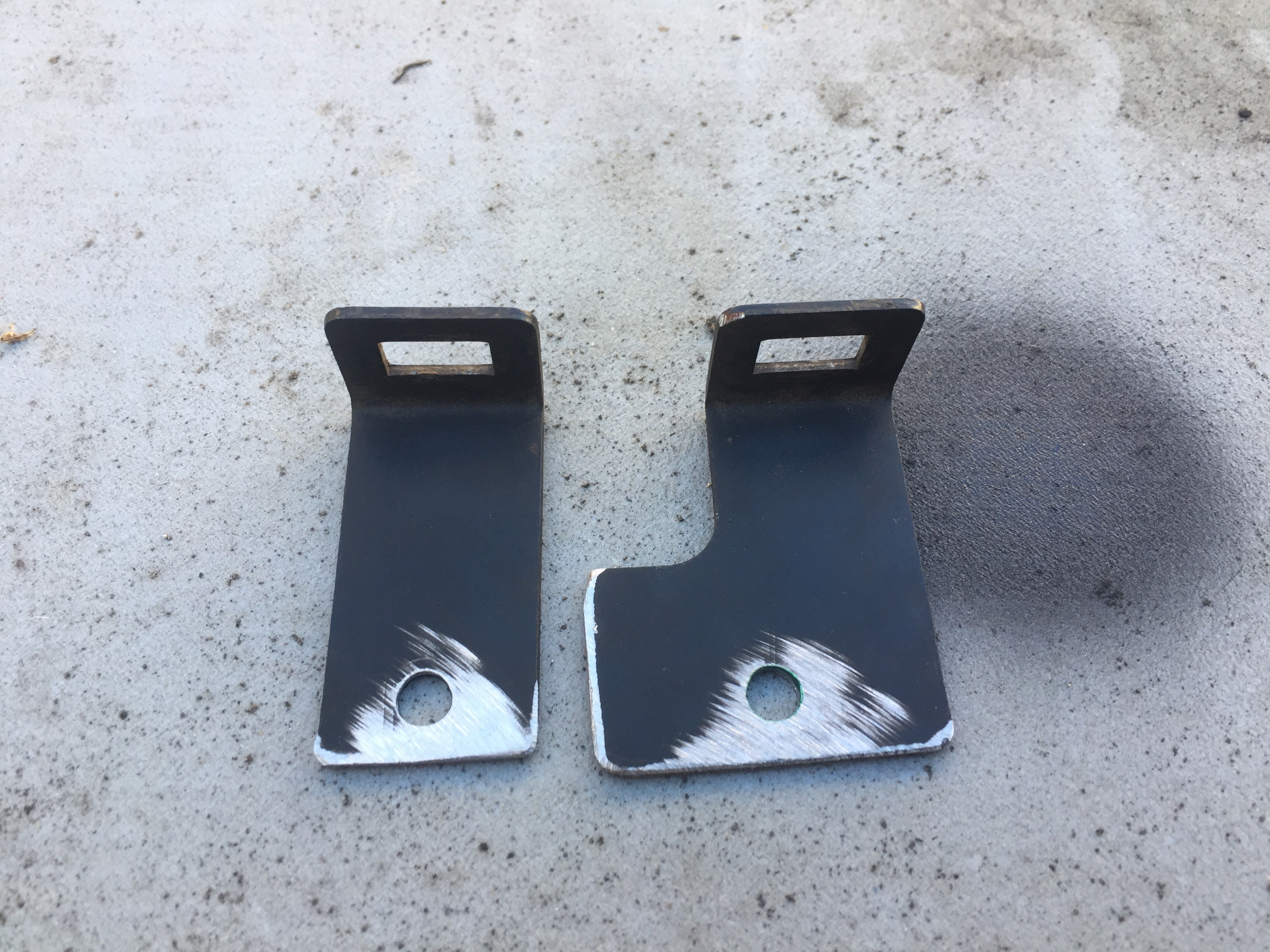
Here is why you want to save those last two brackets. If you purchase one of our cable kits, those two brackets are perfect for mounting your fuse block that comes with the kit to the pinch seam where the un-chopped bracket use to go.
To mount the fuse block, I took the brackets and grinder all the sharp edges and points down. I drilled a 1/4″ hole in each bracket.
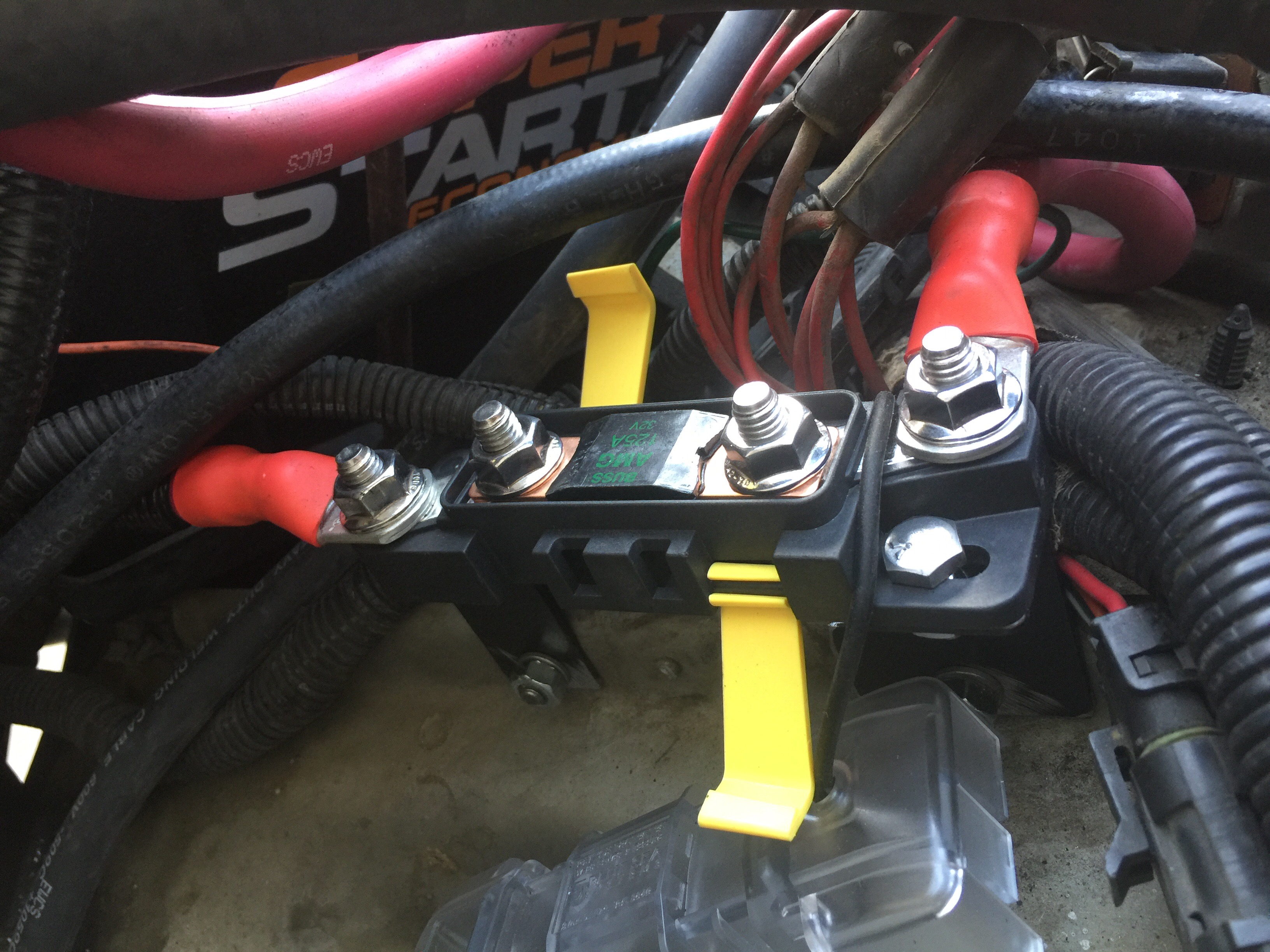
When mounting the fuse block to the brackets, I mounted them 180° out of each other which makes them perfectly straight with each other.


I line the bracket up to the pinch seam on the wheel-well and marked the holes. I drilled the pinch seam and mounted the new “fuse block mount” to the wheel-well pinch seam.
I remounted the fuse block to the bracket, wires the fuse block and checked my clearances between the fuseblock and the overflow bottle.

See, I told you you’d use all those pieces. Check back for more write ups and our future store.
